Geometry and Overlays
Entities
MapLink is often used to display vector data, either in maps or overlays. The underlying geometry model of this vector data is shown below. This model can be directly mapped onto the OpenGIS simple feature model (ignoring the User Geometry Entity). Each piece of geometry stores its coordinates in internal TMC units.
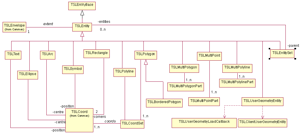
Figure 1 Geometry Hierarchy
The MapLink concept for an instantiated piece of geometry is an Entity. In the 2D SDK, these are accessed through classes derived from TSLEntity. Each different type of geometry has its own class. The TSLEntityBase class provides a common point of derivation for both 2D and 3D geometry.
Note that there is a distinction in MapLink between Geometry and Rendering. The Geometry defines the topography of an object - where it is in the world. The Rendering defines the visualisation of that object. The Geometry is always an inherent part of the Entity, whereas the Rendering may be stored on the Entity, or separately on a Drawing Surface or Data Layer. Rendering is discussed in further detail in section 10.6.
Several primitives define angles for rotation or reference points. These are measured with 0 degrees as the x-axis and positive anti-clockwise.
TSLEntity
This is the base class for all 2D geometric primitives. It gives access to the common methods of all Entity types including rendering definitions; attribute interrogation and cross-Entity spatial queries. It gives no access to the geometric coordinates, since these are dependent upon the derived class.
TSLPolyline
This is a single dimensional line, which has length, but is assumed to have no area. It is typically used to represent such real-world features such as roads, rivers, railways, routes, cables and boundaries. A polyline must have at least two points, but other than that there are no limitations placed upon the coordinates.
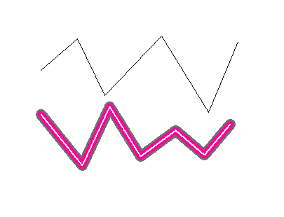
Figure 2 Polyline
TSLPolygon
A polygon is a two-dimensional surface. It therefore has an area and a perimeter. The rendering of a polygon may include a hollow fill so only the edge may be visible. A polygon may have holes, which in MapLink terminology are called ‘inners’. A valid polygon has some restrictions placed upon the geometry so that it conforms to OpenGIS definitions. The coordinates that define the outer or inners of a polygon must have no consecutive duplicate points, and the edges may touch but not cross. The inners must not overlap any other inner, or the outer. MapLink 4.7 and later have additional functionality that removes single-point spikes.
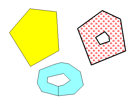
Figure 3 Polygon
MapLink has one important difference from the OpenGIS specification, however. In MapLink, the coordinates of an inner or outer ring may touch along an edge, rather than at a point. This allows for some significant optimisations to be done through key-holing polygons so that they have only an outer ring. This gives increased performance on some platforms.
TSLText
The TSLText object consists of a single position coordinate and a text string. Each text primitive may have a horizontal or vertical alignment which dictates where the text is drawn relative to the specified position. Text may be rotated and sized. Since the font style and scaling have a large effect on the rendering of the piece of text, the extent of the text primitive is held separately for each Drawing Surface that has a unique id.
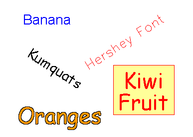
Figure 4 Text
Text primitives in maps are held in a separate sub-layer within the map and are always drawn after the polygons and polylines. This is to prevent text close to tile edges being overwritten by the polygons that exist in the adjoining tile.
A single text object may be split over several lines, by including a carriage return (C++ ‘\n’) character amongst the text. Any alignment and background will take all lines into account.
TSLSymbol
Like TSLText objects, symbols are specified geometrically by a single coordinate. The zoom level of the Drawing Surface and the rendering attributes attached to the Entity can significantly affect the extent of a symbol. Because of this, symbols also hold their extent separately for each uniquely identified Drawing Surface.
Figure 5 Symbols
There are two different types of symbols available in MapLink - vector and raster.
Vector symbols are scalable and are held in individual TMF files - a proprietary MapLink format. They can be created using the Symbol Studio editor available in the MapLink bin directory. Since MapLink 4.5, vector symbols can display text, which may be dynamic (see the section following).
Raster symbols are held in supported image formats (e.g. PNG), with one symbol per file. Note that not all types of drawing surface support scaling of raster symbols or images with an alpha channel.
On Windows, a special subtype of raster symbols that use Windows Icons are available. Icon symbols are displayed as fixed size and may contain an embedded transparency mask so need not be rectangular. Earlier releases can only display standard 32x32 pixel icons - Windows will automatically scale other sizes to fit into 32x32.
Symbol primitives in maps are held in a separate sub-layer within the map and are always drawn after the polygons and polylines. This is to prevent symbols close to tile edges being overwritten by the polygons that exist in the adjoining tile.
Text Replacement
To use the dynamic text features, use Symbol Studio to create a symbol which contains text. If the text is prefixed by a double underscore, this indicates that the text may be dynamic.
The following dynamic text strings are recognised:
- __name
A text string of “__name” will be replaced by the name property of the symbol instance. This is the most efficient way to display a simple textual property within the symbol - e.g. a road name.
At runtime this can be replaced using TSLEntity::name(“text”).
- __entityid
A text string of “__entityid” will be replaced by the numeric Entity ID of the symbol instance. This is the most efficient way to display a simple integer number.
At runtime this can be replaced using TSLEntity::id(number). This may also be set when the entity is created.
- __ID
The text string “__ID” (where ID is any two-character string) will look up the value of the data attribute “ID” from the symbol instance. This allows any embedded data attribute to be displayed. If there is no data attribute found, then the text is not displayed.
This is the two-character ID of an attribute as setup on the TSLDataSet
(see TSLEntityBase::addDataSet).
Following the ‘__’ a valid format string may be added. This will override the defaults as defined below:
__name : %s
__entityid : %I64d
__ID : the default will depend on the mapping.
The name and/or entity ID are sometimes placed on the symbol instance by the MapLink filter. Some filters, such as the ShapeFile and MIF filters, allow you to specify that the name should be populated from attribute in the associated DBF or MID file.
TSLEllipse
A TSLEllipse is a two-dimensional surface that has area and perimeter. It is defined geometrically by the centre point, x and y radial distances and rotation angle. The radial distances are those before rotation is applied. MapLink currently has no facilities for partial ellipses such as chords or sectors. TSLEllipse objects typically do not appear in map data and are unlikely to be produced by MapLink Studio.
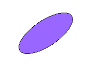
Figure 6 Ellipse
TSLArc
The TSLArc primitive is a one-dimensional curve, which is a portion of the circumference of an ellipse. It therefore has length but no area. It is specified geometrically by the centre of the ellipse, the x and y radial distances and the start and end angle of the sweep. The radial distances and angles are those before rotation is applied. An additional rotation attribute allows the source ellipse to be rotated. The sweep of the arc is anti-clockwise from start angle to end angle. TSLArc objects typically do not appear in map data and are unlikely to be produced by MapLink Studio.
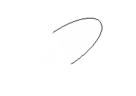
Figure 7 Arc
TSLRectangle
This type of geometric primitive is specified by two corners and a rotation angle. The TSLRectangle may be rotated about its centre.
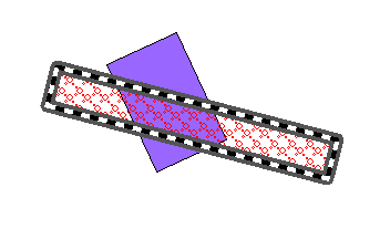
Figure 8 Rectangle
TSLEntitySet and other Collections
This is a collection of other Entities. Note that an Entity Set can contain other Entity Sets and thus be hierarchical. It has no geometric attributes of its own but inherits its envelope as the union of its children’s envelopes.
Unlike OpenGIS collections, a TSLEntitySet can contain different types of TSLEntity.
Simple single-type collections are available via the TSLMultiPolygon, TSLMultiPolyline and TSLMultiPoint classes. These represent a single Entity, and as such the constituent parts only have limited access to the geometry and are not derived from the TSLEntity class.
TSLBorderedPolygon
This is a specialised primitive, often used in Land Registration applications. It is essentially a normal Polygon, but each edge, including those around any holes, has a separate thick border polygon associated with it. This border polygon can be drawn internally or externally to the polygon. Where these border polygons meet, MapLink performs processing to ensure that the join looks aesthetically pleasing.
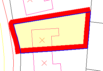
Figure 9 Bordered Polygon
Geodetic Primitives
A geodetic primitive is a primitive whose shape is defined by the projection of the map upon which it is drawn.
Geodetic primitives will be re-drawn if the map projection or map is changed maintaining the positions of the control points in latitude and longitude but changing shape to match the projection.
The shape of a geodetic primitive is defined by interpolating points along a geodesic path, for example; consider the path an aeroplane flies between London and Beijing. Aircraft take the shortest path, the geodesic, between points. In flat space, geodesics are straight lines; on the surface of a sphere, geodesics are the minor arcs of great circles; on the surface of the earth, approximated as an ellipsoid, geodesics are given by Vincenty’s formulae.
The six geodetic primitives currently supported are shown below.
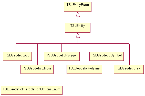
Figure 10 Geodetic Entities Hierarchy
The control points are specified as TMC values, these are then converted to latitude and longitude internally when drawn.
Values of the enumeration TSLGeodeticInterpolationOptionsEnum can be passed to the interpolationOptions method of geodetic polylines, polygons, ellipses and arcs to specify whether to use Vincenty (default) or great circles (TSLGeodeticInterpolationOptionsGreatCircle) to interpolate. For geodetic polylines and polygons, interpolationOptions can also be used to specify whether the earth should be treated as a spheroid (default) or a sphere (with TSLGeodeticInterpolationOptionsSpherical). Multiple flags should be combined with the bitwise OR operator.
TSLGeodeticPolyline
A geodetic polyline is a one-dimensional curve and defined by a sequence of at least two points.
Geodetic polylines optionally support interpolation. When this is turned off, geodetic polylines behave like normal polylines, except for changes in coordinate system. When interpolation is turned on, the lines drawn between control points are interpolated to follow geodesics along the earth’s surface.
If an interpolated geodetic polyline crosses over the dateline, it will be rendered as separate pieces.
Interpolation can be turned on and off with the interpolation method. The post distance used for interpolating, in km, can be set and retrieved with interpolationDistance, and the interpolation method can be set with interpolationOptions.
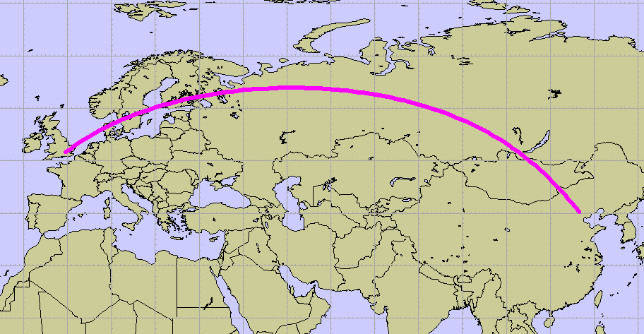
Figure 11 Two-point geodetic polyline, showing the geodesic path from Heathrow to Beijing. A Dynamic Arc map
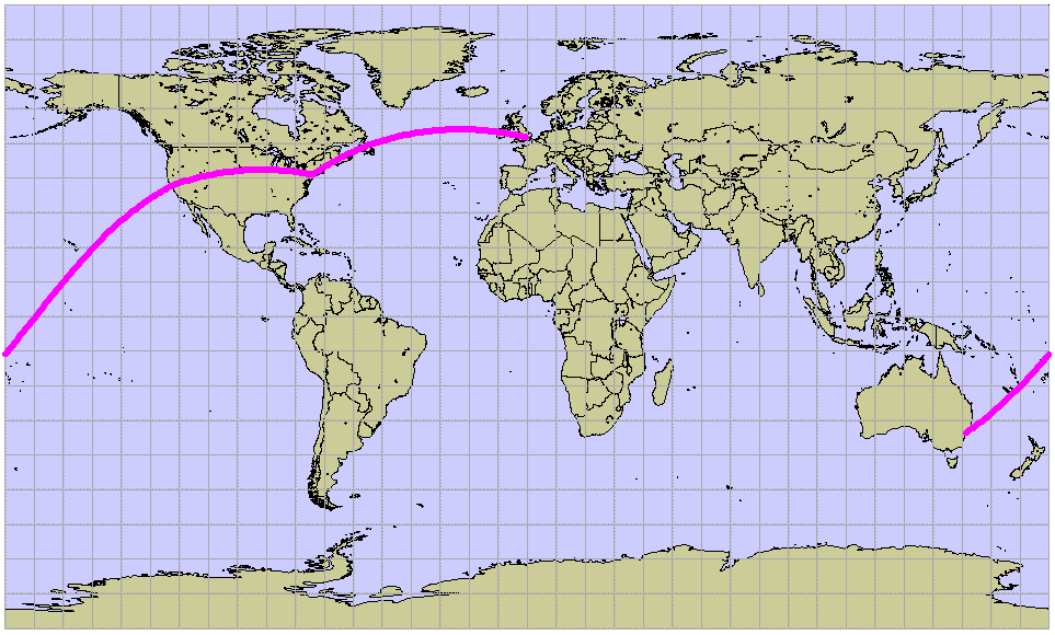
Figure 12 Single geodetic polyline with four points, travelling through Sydney, San Francisco, New York and London.
Geodetic polylines are created in a very similar way to standard polylines:
TSLStandardDataLayer* stdLayer = ...;

TSLDataLayer* mapLayer = ...;

TSLCoordSet* cs = new TSLCoordSet;

TSLTMC x, y;

if ( !mapLayer->latLongToTMC(51.4775, -0.461389, &x, &y) )

... // handle error

cs->add(x, y);

if ( !mapLayer->latLongToTMC(40.08, 116.584444, &x, &y) )

... // handle error

cs->add(x, y);

TSLGeodeticPolyline* polyline = stdLayer->entitySet()->

createGeodeticPolyline( 0, cs, true ) ;

if ( !polyline )

... // handle error

polyline->setRendering( TSLRenderingAttributeEdgeStyle, 1 ) ;

polyline->setRendering( TSLRenderingAttributeEdgeColour,

TSLComposeRGB(255,0,255) ) ;

polyline->setRendering( TSLRenderingAttributeEdgeThickness, 6 ) ;
Geodetic polylines can also be created directly with TSLGeodeticPolyline::create.
TSLGeodeticPolygon
A geodetic polygon is a closed shape and has a perimeter and an area.
Geodetic polygons optionally support interpolation. When this is turned off, geodetic polygons behave like normal polygons, except for changes in coordinate system. When interpolation is turned on, the lines drawn between the control points of the outer are interpolated to follow geodesics along the earth’s surface.
Inners (holes) are not supported.
If an interpolated geodetic polygon crosses over the dateline, it will be rendered as separate pieces. Polygons containing any poles may not be drawn as expected.
Interpolation can be turned on and off with the interpolation method. The post distance used for interpolating, in km, can be set and retrieved with interpolationDistance, and the interpolation method can be set with interpolationOptions.
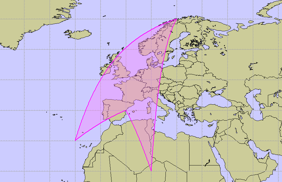
Figure 13 Four-point geodetic polygon
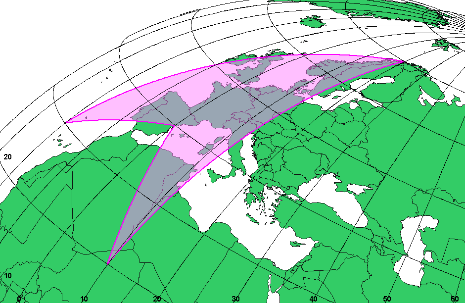
Figure 14 Four-point geodetic polygon reprojected into an orthogonal projection
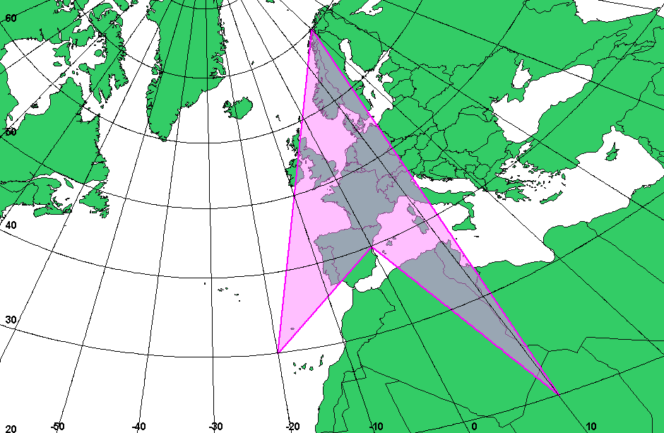
Figure 15 Four-point geodetic polygon, but on a gnomonic projection. In this projection, geodesics are straight lines, so the geodetic polygon looks like a standard polygon. The distortion in its shape is due to the centre of projection being off to one side of the geometry
Geodetic polygons are created in a very similar way to standard polygons:
TSLStandardDataLayer* stdLayer = ...;

TSLDataLayer* mapLayer = ...;

TSLCoordSet* cs = new TSLCoordSet;

TSLTMC x, y;

if ( !mapLayer->latLongToTMC(20.0, 10.0, &x, &y) )

... // handle error

cs->add(x, y);

if ( !mapLayer->latLongToTMC(40.0, 0.0, &x, &y) )

... // handle error

cs->add(x, y);

if ( !mapLayer->latLongToTMC(30.0, -20.0, &x, &y) )

... // handle error

cs->add(x, y);

if ( !mapLayer->latLongToTMC(70.0, 20.0, &x, &y) )

... // handle error

cs->add(x, y);

TSLGeodeticPolygon* polygon = stdLayer->entitySet()->

createGeodeticPolygon( 0, cs, true ) ;

if (!polygon)

... // handle error

polygon->setRendering( TSLRenderingAttributeEdgeStyle, 1 ) ;

polygon->setRendering( TSLRenderingAttributeEdgeColour,

TSLComposeRGB(255,0,255) ) ;

polygon->setRendering( TSLRenderingAttributeEdgeThickness, 2 ) ;

polygon->setRendering( TSLRenderingAttributeFillStyle, 502 ) ;

polygon->setRendering( TSLRenderingAttributeFillColour,

TSLComposeRGB(255,128,255) ) ;
Geodetic polygons can also be created directly with TSLGeodeticPolygon::create.
TSLGeodeticEllipse
A TSLGeodeticEllipse primitive is a two-dimensional surface defined geometrically on the earth’s surface by the centre point, x and y radial distances (in metres, not TMCs) and rotation angle. The radial distances are those before rotation is applied.
Geodetic ellipses are created the same way as standard ellipses, except the x and y radii are floating-point numbers, representing the geodesic distance from the centre in metres. Metres are used because TMCs can distort and wrap around near the edges of maps.
Geodetic ellipses also provide control over the interpolation of their edge. The interpolation step angle, in radians, can be set using interpolationAngleDelta, and the interpolation method can be set with interpolationOptions.
If a geodetic ellipse crosses the dateline, it will be rendered as separate pieces. A geodetic ellipse can cover a pole.
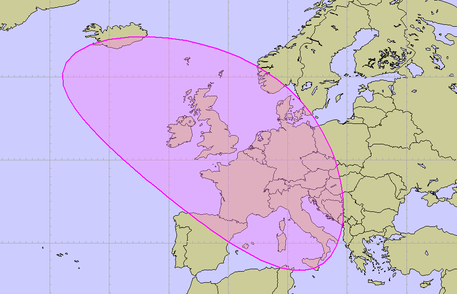
Figure 16 Geodetic ellipse centred on London; x-radius 1000km, y-radius 2000km, rotation 45°.
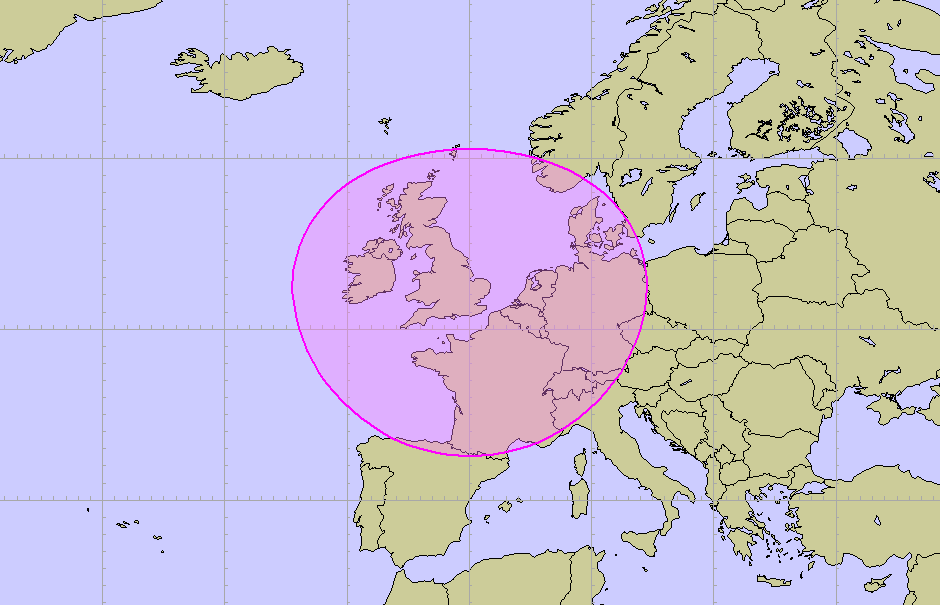
Figure 17 Geodetic ellipse centred on London; x- and y-radius 1000km
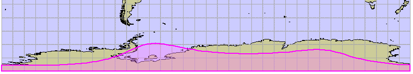
Figure 18 Geodetic ellipse centred on 85°S 0°E; x-radius 1000km, y-radius 2000km, rotation 60°.
Geodetic ellipses are created in a similar way to standard ellipses, except for the radii:
TSLStandardDataLayer* stdLayer = ...;

TSLDataLayer* mapLayer = ...;

TSLTMC x, y;

if ( !mapLayer->latLongToTMC(51.5, 0.05, &x, &y) )

... // handle error

TSLGeodeticEllipse* ellipse = stdLayer->entitySet()->

createGeodeticEllipse( 0, x, y,

1000000.0, 2000000.0, M_PI/4.0 );

if (!ellipse)

... // handle error

ellipse->setRendering( TSLRenderingAttributeEdgeStyle, 1 ) ;

ellipse->setRendering( TSLRenderingAttributeEdgeColour,

TSLComposeRGB(255,0,255) ) ;

ellipse->setRendering( TSLRenderingAttributeEdgeThickness, 2 ) ;

ellipse->setRendering( TSLRenderingAttributeFillStyle, 502 ) ;

ellipse->setRendering( TSLRenderingAttributeFillColour,

TSLComposeRGB(255,128,255) ) ;
Geodetic ellipses can also be created directly with TSLGeodeticEllipse::create.
TSLGeodeticArc
The TSLGeodeticArc primitive is a one-dimensional curve, which is a portion of the circumference of a geodetic ellipse. It therefore has length but no area. It is specified geometrically on the surface of the earth by the centre of the ellipse, the x and y radial distances (in metres, not TMCs) and the start and end angle of the sweep. The radial distances and angles are those before rotation is applied. An additional rotation attribute allows the source geodetic ellipse to be rotated. The sweep of the geodetic arc is anti-clockwise from start angle to end angle.
Geodetic arcs are created the same way as standard arcs, except the x and y radii are floating-point numbers, representing the geodesic distance from the centre in metres.
Geodetic arcs also provide control over their interpolation. The interpolation step angle, in radians, can be set using interpolationAngleDelta, and the interpolation method can be set with interpolationOptions.
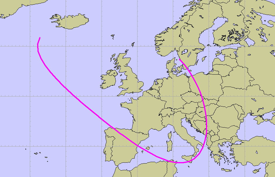
Figure 19 Geodetic arc centred on London; x-radius 1000km, y-radius 2000km, rotation 45°.
Geodetic arcs are created in a similar way to standard arcs, except for the radii:
TSLStandardDataLayer* stdLayer = ...;

TSLDataLayer* mapLayer = ...;

TSLTMC x, y;

if ( !mapLayer->latLongToTMC(51.5, 0.05, &x, &y) )

... // handle error

TSLGeodeticArc* arc = stdLayer->entitySet()->

createGeodeticArc( 0, M_PI/2, 2*M_PI, x, y,

1000000.0, 2000000.0, M_PI/4.0 );

if (!arc)

... // handle error

arc->setRendering( TSLRenderingAttributeEdgeStyle, 1 ) ;

arc->setRendering( TSLRenderingAttributeEdgeColour,

TSLComposeRGB(255,0,255) ) ;

arc->setRendering( TSLRenderingAttributeEdgeThickness, 4 ) ;
Geodetic arcs can also be created directly with TSLGeodeticArc::create.
TSLGeodeticText
A TSLGeodeticText object consists of a single position coordinate and a text string, and behaves identically to a TSLText, except for coordinate system changes.
TSLGeodeticSymbol
A TSLGeodeticSymbol is specified by a single coordinate, and behaves almost identically to a TSLSymbol, except for coordinate system changes.
User Geometry
A user geometry entity allows the user to create custom-drawn geometry upon standard data layers. User geometry can be saved to and loaded from TMF files. A piece of 2D user geometry is composed of two parts, the entity (an instance of TSLUserGeometryEntity, managed by MapLink) and the client (an instance derived from TSLClientUserGeometryEntity, managed by the user).
TSLUserGeometryEntity
Instances of TSLUserGeometryEntity can be added to standard data layers, and are allocated and deallocated by MapLink. Create instances by calling TSLUserGeometryEntity::create, or by calling createUserGeometry on a TSLEntitySet. The client of a user geometry entity can be set and retrieved by calling setClientUserGeometryEntity and getClientUserGeometryEntity, respectively.
create, createUserGeometry, setClientUserGeometryEntity and load callback functions (see section 10.2.3) all provide an ownsClient flag. If true, then MapLink will automatically delete the client if it is replaced with setClientUserGeometryEntity or when the entity is destroyed. If false, the user will have to destroy the client. This must be false if the user’s code is compiled with a different compiler or runtime library version to MapLink.
Creating and destroying user geometry:
TSLStandardDataLayer* stdLayer = ...;

TSLClientUserGeometryEntity* client = new ...;

TSLUserGeometryEntity* entity = stdLayer->entitySet()->

createUserGeometry(client, false);

if (!entity)

... // handle error

...

entity->destroy();

delete client; // don't need this if ownsClient is true
TSLClientUserGeometryEntity
The user creates clients by deriving from TSLClientUserGeometryEntity and creating their own instances of these subclasses. A client can then be attached to an entity as explained above.
At a minimum, the user must override the virtual draw method.
Here is an example partial implementation of a user geometry client:
class RectangleClient : public TSLClientUserGeometryEntity

{

private:

TSLEnvelope m_extent;

public:

// Constructor

RectangleClient(TSLTMC left, TSLTMC bottom, TSLTMC right, TSLTMC top)

{

m_extent.corners( left, bottom, right, top ); // bounding box

}

// Destructor

virtual ~RectangleClient()

{

}

// Draw a rectangle using rendering interface

virtual bool draw(int uniqueSurfaceID,

TSLRenderingInterface* renderingInterface,

const TSLEnvelope& extent, TSLRenderLevel renderLevel,

double screenResolution)

{

const int blue = TSLDrawingSurface::getIDOfNearestColour(0,0,255);

// Construct a rectangle

TSLCoord coords[4]; // bottom left, top left, top right, bottom right

coords[0] = m_extent.bottomLeft();

coords[1] = TSLCoord( m_extent.bottomLeft().x(), m_extent.topRight().y() );

coords[2] = m_extent.topRight();

coords[3] = TSLCoord( m_extent.topRight().x(), m_extent.bottomLeft().y() );

// Set up rendering attributes - translucent rectangle

renderingInterface->setupEdgeAttributes( -1, 0, 0.0 );

renderingInterface->setupAreaAttributes( 503, blue );

// Attempt to draw rectangle, return false if fails

return renderingInterface->drawPolygon(coords, _countof(coords));

}

// Save the rectangle

virtual int save(TSLofstream& stream)

{

// Stream out data

...

return RECTANGLE_USER_GEOMETRY_ID; // unique ID of the user geometry type

}

// Return the envelope for this rectangle

virtual TSLEnvelope envelope(int uniqueSurfaceID)

{

return m_extent;

}

};
Loading and saving user geometry
If the user wants their user geometry classes to be saved and loaded along with other types of geometry, they need to override the save method on the client, and to provide a load callback function to the static method TSLUserGeometryEntity::registerUserGeometryClientLoadCallback.
The save method on the client should return a positive integer to identify the type of user geometry. These numbers should be unique as they can be passed to any registered load callback function. It is suggested that the developer publish and track these identifiers.
It is also suggested that the developer saves, along with any geometry data, a company identifier, a byte-order mark, a geometry type ID and a version number.
To register a load callback function, a pointer to it must be passed to TSLUserGeometryEntity::registerUserGeometryClientLoadCallback. The pointer should have type TSLUserGeometryLoadCallback (which is a function pointer typedef). The pointer will be added to a list; when user geometry is loaded, each function on the list will be called until one returns non-NULL.
Setting a load callback function:
TSLUserGeometryEntity::

registerUserGeometryClientLoadCallback(loadUserGeometryCallback);
Here is a skeleton load callback function:
static TSLClientUserGeometryEntity* loadUserGeometryCallback(

TSLifstream& stream,

int userGeometryID,

bool& assumeOwnership)

{

// whether returned entities will be freed by MapLink:

assumeOwnership = ...;

switch (userGeometryID)

{

case RECTANGLE_USER_GEOMETRY_ID:

... // stream in client and return it

... // etc

default:

return NULL;

}

}
Data Layers
The usual method of displaying fairly static data in MapLink is via the TSLStandardDataLayer. This allows any of the geometric Entities to be displayed and overlaid on top of a map. Of course, you can have any number of Data Layers displayed on a single Drawing Surface, so you are not unduly restricted.
Unlike a TSLMapDataLayer, the TSLStandardDataLayer has no coordinate system of its own. Instead, it uses the coordinate system of the Drawing Surfaces to which it is attached. You should therefore be certain that if the TSLStandardDataLayer is displayed on multiple Drawing Surfaces then they have consistent coordinate systems.
The TSLDrawingSurface assumes the coordinate system of the last TSLMapDataLayer instance added to the surface. This is not necessary the topmost map data layer since the order can be modified by the application.
Each TSLStandardDataLayer contains a TSLEntitySet that is used as a container for the Data Layers Entities. To add Entities to the Data Layer, simply query the Data Layer for its TSLEntitySet and then use the createXxxx methods of the Entity Set. The Entities created will be added to Data Layer and displayed on the next redraw. If you are using double buffering, you should call notifyChanged on the Data Layer to indicate that the contents have changed.
The TSLStandardDataLayer has several storage methods available, for loading and saving its contents via a file or buffer. The buffer or file that is created by this process is a proprietary binary format that may be written to a database blob if required.
It is also possible to load and save the rendering and feature list configuration of the TSLStandardDataLayer. These are the loadDataWithConfig and saveDataWithConfig methods.
Utility Classes used during Entity Creation
There are several classes needed when creating Entities. These are various ways of defining positions and sizes. In general, since the Entities are defined independent of Drawing Surfaces, they use internal TMC coordinate space rather than any particular map coordinate system. If necessary, the coordinate system conversion methods available on Drawing Surfaces and map Data Layers could be used to transform positions into the TMC coordinate space.
A single point is usually specified either by passing individual x, y parameters or by using the TSLCoord utility class. Where an indeterminate number of points must be specified, for example to create a polygon, then an instance of a TSLCoordSet class is most often used. Another commonly used class is TSLEnvelope. This holds two coordinates forming a rectangle and is most often used to pass extents and areas. Full details of the methods available on these classes may be found in the detailed online SDK documentation.
GARS, MGRS and Latitude/Longitude data layers
There are three data layers within MapLink to handle Latitude/Longitude called TSLLatLongGridDataLayer, GARS Grid called TSLGARSDataLayer and Military Grid Reference System (MGRS) and/or the Universal Transverse Mercator (UTM) grid called TSLMGRSGridDataLayer.
The TSLMGRSGridDataLayer
The TSLMGRSGridDataLayer works in two modes, an “automatic” mode and a “single zone” mode. The automatic mode is designed to give reasonable grid lines in all projections, coordinate systems and at any resolution; However, being a general solution it may not be exactly what the user wants. Some projections have very curved grid lines away from the centre of the projection, and there may be errors towards the edge of the map.
The single zone mode is designed to work with transverse Mercator maps in the zone and band specified, although it also will work in other projections.
In general, if you know the MGRS grid zone and band, then the single zone will be more appropriate. For whole world maps or those displayed before the user selects a zone and band, it is best to use the automatic mode. It is possible to turn off the single zone mode by giving it a zone of -1.
The TSLMGRSGridDataLayer may display MGRS, UTM and latitude/longitude grids. Which grids are displayed is controlled by the line and text attributes given below.
The MGRS grid has special features to deal with Scandinavia and is widened to 12 degrees between 72 and 84 degrees north. The latitude / longitude grid incorporates these special features as does the MGRS grid when displayed.
It is also possible to customise the grids displayed, for which grid lines are displayed, the line styles, whether grid squares are named, whether grid lines are labelled and the styles of the text displayed.
For the TSLMGRSGridDataLayer the following lines are configurable:
-
“lon6Degree”
-
“lonDegree”
-
“lonMinute”
-
“lat8Degree”
-
“latDegree”
-
“latMinute”
-
“utm1km”
-
“utm10km”
-
“utm100km”
And the following text labels:
-
“utmLabel”
-
“mgrsLabel”,
-
“gridLineLabel”
-
“degreeLineLabel”
For a grid line to be displayed it must have a colour greater than zero and a thickness greater than zero. For a text label to be displayed, it must have a colour greater than zero.
To configure which grids are displayed:
An MGRS grid is displayed when the “utm1km”, “utm10km” or “utm100km” grid lines are displayed and the “mgrsLabel” is displayed.
A UTM grid is displayed if the MGRS grid is not displayed and the “utm1km”, “utm10km” or “utm100km” grid lines are displayed and the “utmLabel” is displayed.
A lat/long grid is displayed when any of the “lon6Degree”, “lonDegree”, “lonMinute”, “lat8Degree”, “latDegree” or “latMinute” are displayed irrespective of whether either or both the MRGS and UTM grids are displayed.
To create an MGRS Grid Data Layer:
m_mgrsGridLayer = new TSLMGRSGridDataLayer ;

m_mgrsGridLayer->setMapDataLayer(m_mapDataLayer);
To initialise the MGRS grid line styles:
long utm1kmC, utm1kmS, utm1kmT ;

long utm10kmC, utm10kmS, utm10kmT ;

long utm100kmC, utm100kmS, utm100kmT ;

TSLProfileHelper::lookupProfile("gridUtm1kmColour",&utm1kmC,

getIDOfNearestColour( "0,0,127" ) );

TSLProfileHelper::lookupProfile("gridUtm10kmColour",&utm10kmC,

getIDOfNearestColour( "0,0,192" ) );

TSLProfileHelper::lookupProfile("gridUtm100kmColour",&utm100kmC,

getIDOfNearestColour( "0,0,255" ) );

TSLProfileHelper::lookupProfile("gridUtm1kmStyle",&utm1kmS, 6 );

TSLProfileHelper::lookupProfile("gridUtm10kmStyle",&utm10kmS, 3 );

TSLProfileHelper::lookupProfile("gridUtm100kmStyle",&utm100kmS, 1 );

TSLProfileHelper::lookupProfile("gridUtm1kmThickness",&utm1kmT, 1 );

TSLProfileHelper::lookupProfile("gridUtm10kmThickness",&utm10kmT, 1 );

TSLProfileHelper::lookupProfile("gridUtm100kmThickness",&utm100kmT, 2);

m_mgrsGridLayer->setFeatureRendering("utm1km", 0, TSLRenderingAttributeEdgeColour,

utm1kmC);

m_mgrsGridLayer->setFeatureRendering("utm1km", 0, TSLRenderingAttributeEdgeStyle,

utm1kmS);

m_mgrsGridLayer->setFeatureRendering("utm1km", 0, TSLRenderingAttributeEdgeThickness,

(double)utm1kmT);

m_mgrsGridLayer->setFeatureRendering("utm10km", 0, TSLRenderingAttributeEdgeColour,

utm10kmC);

m_mgrsGridLayer->setFeatureRendering("utm10km", 0, TSLRenderingAttributeEdgeStyle,

utm10kmS);

m_mgrsGridLayer->setFeatureRendering("utm01km", 0, TSLRenderingAttributeEdgeThickness,

(double)utm10kmT);

m_mgrsGridLayer->setFeatureRendering("utm100km", 0, TSLRenderingAttributeEdgeColour,

utm100kmC);

m_mgrsGridLayer->setFeatureRendering("utm100km", 0, TSLRenderingAttributeEdgeStyle,

utm100kmS);

m_mgrsGridLayer->setFeatureRendering("utm100km", 0, TSLRenderingAttributeEdgeThickness,

(double)utm100kmT);
To initialise the MGRS grid text styles:
initialiseLabel(m_mgrsGridLayer, "mgrsLabel");

initialiseLabel(m_mgrsGridLayer, "gridLineLabel");
Where the method initialiseLabel sets the following attributes for the text:
TSLRenderingAttributeRenderLevel
TSLRenderingAttributeTextFont
TSLRenderingAttributeTextColour
TSLRenderingAttributeTextSizeFactor
TSLRenderingAttributeTextSizeFactorUnits
TSLRenderingAttributeTextHorizontalAlignment
TSLRenderingAttributeTextVerticalAlignment
TSLRenderingAttributeTextBackgroundMode
TSLRenderingAttributeTextBackgroundColour
TSLRenderingAttributeTextBackgroundEdgeColour TSLRenderingAttributeTextBackgroundStyle
TSLRenderingAttributeTextOffsetUnits
TSLRenderingAttributeTextRotatable
TSLRenderingAttributeTextMinPixelHeight
TSLRenderingAttributeTextMaxPixelHeight
Similarly, the UTM grid lines and labels may be initialised if they are required to be displayed. If the lat/long grid lines and labels are required, they should be initialised too.
Add the TSLMGRSGridDataLayer to the surface and set its visibility.
surface->addDataLayer( m_mgrsGridLayer, m_mgrsGridLayerName ) ;

surface->setDataLayerProps( m_mgrsGridLayerName, TSLPropertyVisible,

m_mgrsGridLayerVisible ) ;
To set the “single zone” mode:
m_mgrsGridLayer->setZone(zone, band);
and back to “automatic” mode:
m_mgrsGridLayer->setZone(-1, 0);
The TSLLatLongGridDataLayer
The TSLLatLongGridDataLayer displays a latitude / longitude grid like that which may be displayed by the TSLMGRSGridDataLayer. However, there are a few differences:
-
The major grid lines are on 6-degree boundaries for both latitude and longitude.
-
Ticks on the grid lines show subdivisions.
-
The special MGRS grid features dealing with Scandinavia are not included.
-
There are different feature classes used. See the class documentation for further details.
To create the TSLLatLongGridDataLayer:
m_latLonGridLayer = new TSLLatLongGridDataLayer ;

m_latLonGridLayer->setMapDataLayer(m_mapDataLayer);
To enable ticks on the grid lines showing divisions:
m_latLonGridLayer->ticks(true);
The TSLGARSGridDataLayer
This draws a GARS (Global Area Reference System) grid.
More information about the GARs Grid can be found here:
http://earth-info.nga.mil/GandG/coordsys/grids/gars.html.
Additional Data Layers
Custom Data Layer
The Custom Data Layer concept allows Developers to draw complex content themselves. A Custom Data Layer has the following features:
-
The layer can be a coordinate providing layer, for example a TSLMapDataLayer is a coordinate providing layer.
-
Support for editing of MapLink geometry.
-
Ability to notify the Drawing Surface of the ideal Active layer (required for 3D and Accelerator SDK).
-
Ability to contain other MapLink 2D layers and draw them when required by the application. This is a concept similar to a TSLMapDataLayer which can contain multiple layers (different resolutions).
-
Access to the screen resolution and layer properties (TSLPropertyEnum).
-
Ability to drawing data using Native drawing code of the TSLRenderingInterface.
This functionality permits users to create their own layer to support, for example, proprietary Web Map Servers (ones which do not conform to the OGC WMS Standard) or display of Vector data from a WFS server (see the “WFS Client SDK”).
The MapLink Pro team has extensive experience creating specific visualisation layers. If you require a project specific layer then please contact Sales to discuss the possibility for consultancy to help implement a layer.
Standard Data Layer
This is a standard component.
This layer is for user created geometry overlays. The layer is covered in section 11.
Dynamic Data Object Layer
This is a standard component.
This layer is designed for displaying large numbers of tracks. The layer is covered in section 14.
S57/S63 Data Layer
This layer is an optional component.
The layer follows the IHO S63 specification and provides an OEM the ability to create a compliant solution for displaying S63 data.
CADRG Data Layer
This layer is an optional component.
The layer provides the ability to display CADRG/CIB data directly within an application using the 2D Drawing surfaces including the Accelerator surfaces and the 3D Drawing Surface.
WMS DataLayer
This is a standard component.
This layer allows you to display data from WMS Servers using 2D Drawing surfaces including the Accelerator surfaces and the 3D Drawing Surface. See section 12.13.
WMTS DataLayer
This is a standard component.
This layer allows you to display data from WMS Servers using 2D Drawing surfaces including the Accelerator surfaces.
KML DataLayer
This is a standard component.
This layer allows you to display KML/KMZ data using 2D Drawing surfaces including the Accelerator surfaces. Please see the sample for additional information.
Filter Data Layers
Filter Data Layers are essentially mini MapLink Studio layers that allow users to direct import data, re-projection and save the results. The layer only offers a subset of data processing options. See section 12.12.
If the filter you wish to use is not currently supported, please contact sales to discuss.
Raster Filter Data Layer
This is a standard layer.
This layer provides access to the Raster filter and the GeoTIFF filter.
NITF Filter Data Layer
This is an optional component.
This layer provides access to the NITF filter.
The NITF Filter Data Layer is configured in a similar way as the Raster Filter Data Layer. Please see the previous section for an example.
Direct Import Data layer
This is a standard component.
This layer allows users to load a wide variety of data formats at runtime in a scalable and performant manner. See section 14.
Rendering Configuration
Rendering is a term used for the graphical properties used to define the visual appearance of an Entity. MapLink has very powerful and flexible facilities for visualisation. Rendering may be defined in three different places - on individual Entities, on Data Layers or on Drawing Surfaces. The first method is commonly called ‘Entity Based rendering’ whilst the other methods are ‘Feature Based rendering’.
Many of the rendering attributes refer to configuration files such as ‘tsllinestyles.dat’. See section 12.6 for further details about the contents of these files.
Rendering Attributes
Wherever they are defined, the graphical properties are split into 5 categories and 3 types.
Generic Attributes
These are available on all Entities, regardless of type.
-
TSLRenderingAttributeFeatureID: Signed 32-bit value, user defined features may be from 1 to 16777215 (0xFFFFFF). This value is used to lookup feature based rendering that may be applied to an Entity. The default is 0.
-
TSLRenderingAttributeRenderLevel: Valid values are -5 to +5. The default is 0.
-
TSLRenderingAttributeVisible: Boolean flag which indicates whether the Entity should be drawn. The default is true.
-
TSLRenderingAttributeSelectable: Boolean flag that indicates whether the Entity can be found when selecting objects using the Editor SDK or when searching the data using the find and query methods of the Drawing Surface and Data Layer. Note that the Data Layer properties TSLPropertyDetect and TSLPropertySelect are also considered when searching and selecting. The default is true.
-
TSLRenderingAttributeReadOnly: Boolean flag that indicates whether the attributes defined on an Entity are read-only. This flag can be used to inhibit modification through the Editor SDK. Of course, this attribute itself cannot be read-only otherwise it cannot be turned off! The default is false.
Line Rendering Attributes
These are available on one-dimensional Entities such as Polylines and Arcs. They are:
-
TSLRenderingAttributeEdgeColour: This value must be an index from the tslcolours.dat file, the currently loaded map palette or a 24-bit colour (see TSLColourHelper API Documentation). The default is -1, which inhibits display of the Entity.
-
TSLRenderingAttributeEdgeStyle: This value must be an index from the tsllinestyles.dat file. The default is -1, which inhibits display of the Entity.
-
TSLRenderingAttributeEdgeThicknessUnits: This value must be one of the TSLDimensionUnits enum values. Use of this attribute allows the line thickness to be defined in device units, internal TMC units, map units or points (1/72 of an inch). The default is TSLDimensionUnitsPixels.
-
TSLRenderingAttributeEdgeThickness: This value is in the units defined by the TSLRenderingAttributeEdgeThicknessUnits value. It is a floating-point number so when applicable may hold fractional values. Note that complex and multi-pass line styles have a minimum device unit thickness in order to maintain a coherent display. If an attempt is made to set a smaller thickness, or a variable thickness line produces a smaller value, then the minimum is used. The default is -1, which inhibits display of the Entity.
Area Rendering Attributes
These are available on two-dimensional Entities such as Polygons, Ellipses and Rectangles. The rendering for the edges of areas are different from those used for lines - this is because there may be both lines and area features assigned the same feature code. The current area rendering attributes are:
-
TSLRenderingAttributeFillColour: This value must be an index from the tslcolours.dat file, the currently loaded map palette or a 24-bit colour (see TSLColourHelper API Documentation). The default is -1, which inhibits display of the fill potentially leaving just the edge of the Entity.
-
TSLRenderingAttributeFillStyle: This value must be an index from the tslfillstyles.dat file. The default is -1, which inhibits display of the fill potentially leaving just the edge of the Entity.
-
TSLRenderingAttributeExteriorEdgeColour: This value must be an index from the tslcolours.dat file, the currently loaded map palette or a 24 bit colour (see TSLColourHelper API Documentation). Note that this also applies to the edges of any holes in a polygon. The default is -1, which inhibits display of the edge potentially leaving just the fill of the Entity.
-
TSLRenderingAttributeExteriorEdgeStyle: This value must be an index from the tslinestyles.dat file. Note that this also applies to the edges of any holes in a polygon. The default is -1, which inhibits display of the edge potentially leaving just the fill of the Entity.
-
TSLRenderingAttributeExteriorEdgeThicknessUnits: This value must be one of the TSLDimensionUnits enum values. Use of this attribute allows the edge thickness to be defined in device units, internal TMC units, map units or points (1/72 of an inch). Note that this also applies to the edges of any holes in a polygon. The default is TSLDimensionUnitsPixels.
-
TSLRenderingAttributeExteriorEdgeThickness: This value is in the units defined by the TSLRenderingAttributeExteriorEdgeThicknessUnits value. It is a floating point number so where relevant may hold fractional values. Note that complex line styles have a minimum device unit thickness in order to maintain a coherent display. If an attempt is made to set a smaller thickness, or a variable thickness line produces a smaller value, then the minimum is used. Note that this also applies to the edges of any holes in a polygon. The default is -1, which inhibits display of the edge potentially leaving just the fill of the Entity.
-
TSLRenderingAttributeBorderWidth: This value, in internal TMC units, is the width of the internal or external border of a TSLBorderedPolygon object. It has no effect on a normal polygon. This may be displayed in addition to the standard edge of the polygon. A value of 0 indicates that no border is displayed. Under these circumstances, a TSLBorderedPolygon is displayed as a normal TSLPolygon.
-
TSLRenderingAttributeBorderColour: This value must be an index from the tslcolours.dat file, the currently loaded map palette or a 24 bit colour (see TSLColourHelper API Documentation). It defines the colour of the internal or external border of a TSLBorderedPolygon. The default is -1, which inhibits display of the border and hence it is displayed as a normal TSLPolygon.
Text Rendering Attributes
These are available on Text Entities. They are:
-
TSLRenderingAttributeTextColour: This value must be an index from the tslcolours.dat file, the currently loaded map palette or a 24 bit colour (see TSLColourHelper API Documentation). The default is -1, which inhibits display of the Entity.
-
TSLRenderingAttributeTextFont: This value must be an index from the tslfonts.dat file. The default is -1, which inhibits display of the text. Note that the contents of the tslfonts.dat file are operating system dependant and so may not give an exact match if displayed on different machines.
-
TSLRenderingAttributeTextSizeFactor: This value defines the size or height of the Text. It may also be adjusted by the height defined on the TSLText object itself. This is a floating point number, whose units are defined by TSLRenderingAttributeTextSizeFactorUnits. The default is 0, which inhibits display of the text.
-
TSLRenderingAttributeTextSizeFactorUnits: This value is one of TSLDimensionUnits enum, and determines how the TSLRenderingAttributeTextSizeFactor value is interpreted. Typical values allow the height of the text to be defined in points, Map Units, internal TMC units or device units. An additional value for text and symbol size factors is TSLDimensionUnitsScaleFactor. This makes MapLink calculate the actual size of the object by multiplying the TSLRenderingAttributeTextSizeFactor by the TMC height stored on the Entity. This facility is included mainly for backwards compatibility and it is recommended that new code does not use this. However, again for backwards compatibility, the default is TSLDimensionUnitsScaleFactor!
-
TSLRenderingAttributeTextMinPixelHeight: This value defines the minimum height, in pixels, that the Text will be displayed at. It may be used for clamping text height within certain boundaries to maintain visibility. If a simple fixed pixel size is required, then use Size Factor Units of Pixels and set the Size Factor to be the required pixel height. The default value is 1. Note that the text may be made invisible before this value is reached, using the TSLDrawingSurface::setDataLayerProps method and the TSLPropertyMinTextHeight property.
-
TSLRenderingAttributeTextMaxPixelHeight: This value defines the maximum height, in pixels, that the Text will be displayed at. It may be used for clamping text height within certain boundaries to maintain visibility. If a simple fixed pixel size is required, then use Size Factor Units of Pixels and set the Size Factor to be the required pixel height. The default value is 2000 pixels. Note that the text may be made invisible before this value is reached, using the TSLDrawingSurface::setDataLayerProps method and the TSLPropertyMaxTextHeight property.
-
TSLRenderingAttributeTextOffsetX: This is the horizontal offset of the text, relative to its defined position, in addition to the alignment. This is typically used for positioning of text that has been generated relative to a point object in a map. The default value is 0. The value is interpreted according to the value of the TSLRenderingAttributeTextOffsetUnits property.
-
TSLRenderingAttributeTextOffsetY: This is the vertical offset of the text, relative to its defined position, in addition to the alignment. This is typically used for positioning of text that has been generated relative to a point object in a map. The default value is 0. The value is interpreted according to the value of the TSLRenderingAttributeTextOffsetUnits property.
-
TSLRenderingAttributeTextOffsetUnits: This value is one of TSLDimensionUnits enum, and determines how the TSLRenderingAttributeTextOffsetX/Y values are interpreted. Typical values allow the offset of the text to be defined in Map Units, internal TMC units or device units. To keep positioning constant relative to any underlying map or associated symbol, this is usually the same as the SizeFactorUnits. The default is TSLDimensionUnitsUndefined, which in this case is interpreted as pixels.
-
TSLRenderingAttributeTextVerticalAlignment: Value is one of TSLVerticalAlignment enum. This value is only used if no alignment is stored on the Entity. This is because some map data sources, such as Ordnance Survey NTF, include topographic text with defined alignments and rotations. For this rendering attribute to have any effect, the alignment stored on the Entity must be TSLVerticalAlignmentUndefined.
-
TSLRenderingAttributeTextHorizontalAlignment: Value is one of TSLHorizontalAlignment enum. This value is only used if no alignment is stored on the Entity. This is because some map data sources, such as Ordnance Survey NTF, include topographic text with defined alignments and rotations. For this rendering attribute to have any effect, the alignment stored on the Entity must be TSLHorizontalAlignmentUndefined.
TSLRenderingAttributeTextBackgroundMode: Value is one of TSLTextBackgroundMode enum. This attribute allows text to be rendered with some form of background. Currently this may be in the form of a dynamically resizing rectangle, or a single pixel outline or halo around the text.
The rectangle fill colour, fill style and edge colour may be configured using other rendering attributes but will always have a solid edge. The rectangle will dynamically resize to fit around the text and will automatically compensate for multiple lines, alignment and text size changes and will rotate will the text.
The halo effect may be applied to either raster or Hershey vector text and will always be a single pixel in the configured text background colour. This effect renders the text multiple times, so it can have a performance hit. We recommend that you verify the performance on your target system.
The default value is TSLTextBackgroundModeNone.
-
TSLRenderingAttributeTextBackgroundColour: This value must be an index from the tslcolours.dat file, the currently loaded map palette or a 24-bit colour (see TSLColourHelper API Documentation). When using rectangle backgrounds, this attribute defines the fill colour. When using halo backgrounds, this attribute defines the outline colour. The default is -1, which inhibits display of the background.
-
TSLRenderingAttributeTextBackgroundStyle: Value is index from tslfillstyles.dat file. This attribute is ignored for halo backgrounds but defines the fill style for rectangle backgrounds. The default is -1, which inhibits display of the background fill.
-
TSLRenderingAttributeTextBackgroundEdgeColour: This value must be an index from the tslcolours.dat file, the currently loaded map palette or a 24-bit colour (see TSLColourHelper API Documentation). The default is -1, which inhibits display of any background rectangle edge.
-
TSLRenderingAttributeTextFixedHeight: Deprecated, use TSLRenderingAttributeTextScaleFactor with TSLRenderingAttributeTextScaleFactorUnits of TSLDimensionUnitsPixels instead. If used, this attribute will force the text to be drawn with the Text Entity height attribute defining the pixel size.
-
TSLRenderingAttributeTextRotatable: This boolean flag enables or disables rotation of text. If the flag is false, then the rotation of the text Entity and the Drawing Surface are both ignored when rendering the text. This is often used to inhibit rotation that has been added to map text due to coordinate system transformations. The default value is true.
Many of these attributes are interdependent.
The size of the font used to render the text is calculated using the following pseudo-code:
if ( obsolete fixed size flag is true )

{

sizeInPixels = Entity size

}

else

{

switch ( textSizeFactorUnits )

{

case pixels :

sizeInPixels = size factor

case map units :

sizeInPixels = (size factor * tmcPerMU) / tmcPerDU

case scale factor :

sizeInPixels = (Entity size * size factor ) / tmcPerDU

}

}

if ( sizeInPixels < minHeight )

sizeInPixels = minHeight ;

else if ( sizeInPixels > maxHeight )

sizeInPixels = maxHeight ;
Symbol Rendering Attributes
These are available on Symbol Entities. They are:
-
TSLRenderingAttributeSymbolColour: This value must be an index from the tslcolours.dat file, the currently loaded map palette or a 24-bit colour (see TSLColourHelper API Documentation). The default is -1, which inhibits display of the Entity.
-
TSLRenderingAttributeSymbolStyle: This value must be an index from the tslsymbols.dat file. The default is -1, which inhibits display of the symbol. Note that the icon symbols defined in the standard tslsymbols.dat file cannot currently be displayed on X11 based systems.
-
TSLRenderingAttributeSymbolSizeFactor: This value defines the size or height of the Symbol. It may also be adjusted by the height defined on the TSLSymbol object itself. This is a floating-point number, whose units are defined by TSLRenderingAttributeSymbolSizeFactorUnits. The default is 0, which inhibits display of the Symbol.
-
TSLRenderingAttributeSymbolSizeFactorUnits: This value is one of TSLDimensionUnits enum and determines how the TSLRenderingAttributeSymbolSizeFactor value is interpreted. Typical values allow the height of the Symbol to be defined in points, Map Units, internal TMC units or device units. An additional value for text and symbol size factors is TSLDimensionUnitsScaleFactor. This makes MapLink calculate the actual size of the object by multiplying the TSLRenderingAttributeSymbolSizeFactor by the TMC height stored on the Entity. This facility is included mainly for backwards compatibility and it is recommended that new code does not use this. However, again for backwards compatibility, the default is TSLDimensionUnitsScaleFactor!
-
TSLRenderingAttributeSymbolMinPixelHeight: This value defines the minimum height, in pixels, that the Symbol will be displayed at. It may be used for clamping Symbol height within certain boundaries to maintain visibility. If a simple fixed pixel size is required, then use Size Factor Units of Pixels and set the Size Factor to be the required pixel height. The default value is 1.
-
TSLRenderingAttributeSymbolMaxPixelHeight: This value defines the maximum height, in pixels, that the Symbol will be displayed at. It may be used for clamping Symbol height within certain boundaries to maintain visibility. If a simple fixed pixel size is required, then use Size Factor Units of Pixels and set the Size Factor to be the required pixel height. The default value is 2000 pixels.
-
TSLRenderingAttributeSymbolRotatable: Value is one of TSLSymbolRotation enum. This is more than a simple boolean flag, in order to maintain backwards compatibility. The tslsymbols.dat file contains a flag for each symbol indicating whether by default it should be rotatable. For example, a lighthouse symbol should remain vertical, whereas a flow arrow must be rotated to indicate the direction of flow. If your application is using the symbols in an unusual way - for example using a (non-rotatable) “airport” symbol to represent a moving “aircraft” track, then you may wish to override the standard settings.
The TSLSymbolRotation enum allows you to specify that the symbol will be rotatable, not rotatable, or that the default rotatability defined in the tslsymbols.dat file should be used.
-
TSLRenderingAttributeSymbolFixedSize: Deprecated, use TSLRenderingAttributeSymbolScaleFactor with TSLRenderingAttributeSymbolScaleFactorUnits of TSLDimensionUnitsPixels instead. If used, this attribute will force the Symbol to be drawn with the Entity height attribute defining the pixel size.
-
TSLRenderingAttributeRasterSymbolScalable: Value is one of TSLRasterSymbolScalability enum. This is more than a simple boolean flag, in order to maintain backwards compatibility. By default, raster symbols are not scalable and are displayed at their relevant pixel size regardless of the calculated height of the symbol. This rendering attribute allows an application to enable scaling for this raster symbol.
-
TSLRenderingAttributeSymbolFontCharacter: Symbols may be characters from a font. The font is referenced via an entry in the tslsymbols.dat file. For such symbol styles, this rendering attribute defines the character from the font to be displayed.
The size of the symbol used to render the text is calculated using the following pseudo-code:
if ( obsolete fixed size flag is true )

{

sizeInPixels = Entity size

}

else

{

switch ( symbolSizeFactorUnits )

{

case pixels :

sizeInPixels = size factor

case map units :

sizeInPixels = (size factor * tmcPerMU) / tmcPerDU

case scale factor :

sizeInPixels = (Entity size * size factor ) / tmcPerDU

}

}

if ( sizeInPixels < minHeight )

sizeInPixels = minHeight ;

else if ( sizeInPixels > maxHeight )

sizeInPixels = maxHeight ;
Raster Icon Symbols
Some of the symbols defined in the default tslsymbols.dat file are raster icons. These are standard windows .ico files. These have certain limitations which you should be aware of before using them:
-
They are usually drawn fixed size. Regardless of the Symbol size rendering attributes, they will always be drawn as they are defined. This behaviour can be overridden using the TSLRenderingAttributeRasterSymbolScalable attribute.
-
They cannot be rotated, and any rotation applied to the Symbol will be ignored.
-
A .ico file may contain multiple icons. Only the first one will be used.
-
The .ico file can contain icons of any size, but due to issues in the underlying Windows API, there will be a significant performance hit if either the width or height values are not multiples of 8. The transparency facility of the icon format can be used to mask out any additional pixels.
-
Icon Symbols may be displayed on X11 based platforms (See the X11 Release Notes).
-
The extent of the Symbol will include the full size of the icon, not just the non-masked areas.
Other Raster Symbols
It is possible to use other custom raster objects as symbols. These have certain limitations which you should be aware of before using them:
-
They are usually drawn fixed size. Regardless of the Symbol size rendering attributes, they will always be drawn as they are defined. This behaviour can be overridden using the TSLRenderingAttributeRasterSymbolScalable attribute.
-
Raster symbol rotation is only supported by the OpenGL 2D drawing surface. When using any other type of drawing surface rotation applied to the symbol will be ignored.
-
When using raster symbols containing transparency, the TSLNTSurface and TSLMotifSurface may convert the transparency information in the image to an on/off mask.
-
The extent of the Symbol will include the full size of the image, not just the non-masked areas.
Entity Based Rendering
Each Entity within MapLink may have its own unique rendering defined. This takes precedence over any Feature Based Rendering that may have been configured and is typically used for overlays in a TSLStandardDataLayer and for Entities created using the Editor SDK.
Entity Based Rendering is configured using the TSLEntity::setRendering methods. These are a group of three overloaded methods with a single simple interface. The methods take an enumeration defining the graphical property to set, along with the new value. There is also a parallel set of query methods.
Feature Based Rendering
Maps often contain lots of Entities that need to be rendered in a similar fashion. Feature Based Rendering allows the rendering styles to be defined once only for a particular map feature type and then specific Entities to be tagged with an identifier to indicate what feature type it represents. This saves memory and improves performance since the rendering styles need only be stored once and optimisations can be made to the low-level graphics calls when all features of a particular type are drawn together.
As an example of Feature Based Rendering, MapLink may be told that features of type “A Road” are to be drawn as red lines with black edges, and individual Entities are tagged as being an “A Road”. In a map, the rendering is usually configured within MapLink Studio, using the Feature Book. In a run-time application, it may be configured on the TSLDrawingSurface or on the TSLDataLayer. Wherever Feature Based Rendering is configured, it uses the same setFeatureRendering methods. These are a group of three overloaded methods with a single simple interface. The methods take the feature name, feature ID and an enumeration defining the graphical property to set, along with the new value. There is also a parallel set of query methods. Note that the feature name is optional. If NULL is passed, the feature ID is used.
Determining the Source of Rendering Attributes
As described above, there are multiple places to define the Rendering Attributes of an Entity. MapLink must determine where to fetch the attributes from at run-time.
When rendering an Entity, MapLink first of looks to see if there is any Entity Based Rendering defined on the Entity. If so, then that is used. If none exists, then the Feature ID stored on the Entity is used to search for Feature Based Rendering on the TSLDrawingSurface currently being drawn. If none exists on the TSLDrawingSurface then the TSLDataLayer is searched. If there is also no Feature Based Rendering defined there, then the process begins again starting at the parent of the Entity - the TSLEntitySet that contains it.
If MapLink cannot determine the Rendering Attributes, the Entity is not drawn. All Rendering Attributes for an Entity will be taken from the same place. For example, it is not possible to define the Edge Colour of a polyline using Entity Based Rendering and the Edge Style using Feature Based Rendering.
Determining Styles and Font Indices
Many different symbols, fonts, line styles and fill styles are supplied with MapLink. The easiest way to see the available styles, and to determine their index, is to look in the MapLink Studio Feature Book.
-
Start a new map project and invoke the Feature Book.
-
Select the Reference Section, Layer Overview Feature.
-
Each index-based property in the Feature Properties Dialog shows a sample of the current rendering, a description and the index for that style. You may need to make the Feature Properties Dialog wider to see the index - especially for some of the complex line styles which can have very long descriptions.
-
Using the Feature Properties Dialog, browse the available styles to find an appropriate one and select it. Some properties display the index in the combo box used for selection. Other properties such as colour and symbol style do not display the index during selection.
-
The Feature Properties Dialog will be updated to show the index of your chosen style.
-
Where a particular style has multiple colours displayed, such as vector symbols or complex line styles, the configurable colour is displayed as red in the sample.
Minimum Attribute Requirements
Many of the default values inhibit display of the Entity until explicitly set by the user. To enable display of the various Entity types, the following rendering attributes must be set - either through Entity Based Rendering or through Feature Based Rendering:
-
TSLPolyline and TSLArc: Requires style, colour and thickness to be set. By default, the thickness is in pixels.
-
TSLPolygon, TSLEllipse, TSLRectangle and TSLBorderedPolygon: A visible fill requires style and colour to be set. A visible edge requires style, colour and thickness to be set. By default, the thickness is in pixels.
-
TSLText: Requires a height stored on the Entity of > 0, a font, a colour and a size factor. The default size factor units will multiply the Entity height by the size factor to determine the TMC height of the Text.
-
TSLSymbol: Requires a style, colour and size factor. The default size factor units will multiply the Entity height by the size factor to determine the TMC height of the Symbol.
Why Can’t I See My Object?
One of the most frustrating things that can happen when developing an application is when you expect something to happen, but it doesn’t. A typical example of this in a MapLink application is an Entity not appearing when it is created. There can be many reasons for the non-appearance and it can be difficult to track down. Here is a list of the most common reasons:
-
The Entity was never actually created. This can occur if invalid arguments are passed to the create method call - such as an empty string being passed to createText or a self-intersecting coordinate set being passed to createPolygon. Check the return value from the create call and look at the contents of the error stack to see what may have gone wrong.
-
The Entity has no Rendering Attributes associated with it. These can either be configured on the Entity itself, or on the Data Layer or Drawing Surface via Feature Based Rendering. See Section 11 for code examples of some simple rendering configurations. The Geometry Creation sample installed with MapLink gives examples of every available Rendering Attribute for each primitive type and allows you to experiment with them. Note that this sample also includes access to obsolete attributes which may clash with other newer ones!
-
The Entity has insufficient Rendering Attributes associated with it. Even though an Entity may have some attributes, they may not be enough to create a valid rendition. See Section 10.6.13 for a list of the minimum set of Rendering Attributes for each primitive type.
-
The associated Rendering Attributes are illegal. This means that an index is not found in the associated configuration file. For example, a colour index that is not in the current palette, a line style index that does not exist in tsllinestyles.dat, a symbol style index that specifies an icon symbol may be illegal on X11 as are some fonts (See X11 Release Notes). Check the contents of the configuration files (see Section 12.6) or validate the styles in MapLink Studio.
-
Would the Rendering Attributes give a visible representation anyway? Some of the line styles and fill styles give no rendition - such as hollow, highly translucent or very sparse bitmap fill styles.
-
Is the Entity in a TSLEntitySet that is associated with a Data Layer? Free-floating Entities are never displayed. They need to be inserted into a TSLStandardDataLayer. Is the Data Layer associated with the Drawing Surface?
-
Has notifyChanged been called on the Data Layer after the Entity is created? Without this, the Data Layer does not invalidate any associated buffer and so the old contents are used when drawing an unchanged view extent.
-
Is the Entity, its parent Entity Sets and associated Data Layer all visible? An Entity can be hidden using TSLRenderingAttributeVisible and a Data Layer can be hidden using TSLPropertyVisible.
-
Have the Entity or Data Layer been decluttered? An Entity can be decluttered and thereby hidden, using the setDeclutterStatus method of the Drawing Surface. A Data Layer can be hidden according to zoom level using the TSLPropertyMinZoomDisplay and TSLPropertyMaxZoomDisplay properties.
-
Is the Drawing Surface actually viewing the area containing the Entity?
For Text primitives, have they been hidden because they are too small or too big? These limits default to 3 pixels and 200 pixels. They can be configured using TSLPropertyMinTextHeight and TSLPropertyMaxTextHeight.