OpenGL Drawing Surface
The OpenGL drawing surface allows an application to take advantage of hardware acceleration to enable high performance visualisations on both desktop and mobile platforms. In many circumstances it can be used as a drop-in replacement for the GDI-based and X11-based drawing surfaces from the Core SDK.
Library Usage and Configuration
As of version 11.1, MapLink is no longer supplied with Debug or 32-bit libraries. Therefore, your application’s build should link against the Release Mode libraries in all configurations.
| MapLinkOpenGLSurface64.lib Release mode, DLL version. Uses Multithreaded DLL C++ run-time library. Must also link the MapLink CoreSDK library MapLink64.lib Requires TTLDLL preprocessor directive. Refer to the document “MapLink Pro X.Y: Deployment of End User Applications” for a list of run-time dependencies when redistributing. Where X.Y is the version of MapLink you are deploying. |
Hardware Requirements
The OpenGL surface requires OpenGL 2.1 or later (for desktop) or OpenGL ES 2.0 (for mobile/embedded) compliant hardware in order to function. Systems that do not meet this requirement should use either the TSLNTSurface on Windows or the TSLMotifSurface on X11 platforms.
Note: Integrated motherboard chipsets, such as Intel Integrated Graphics, should be avoided if at all possible for desktop/laptop applications.
The table below lists any additional extensions that will be used by the surface depending on the OpenGL version it is running on. Recommended extensions are not required for the surface to operate but may have a negative impact on performance or functionality if not present.
| OpenGL Version | Required Extensions | Recommended Extensions |
|---|---|---|
| 2.1 | EXT_framebuffer_object or ARB_framebuffer_object | NV_primitive_restart^1^ ARB_texture_multisample^2^ |
| 3.2 | None | EXT_direct_state_access^1^ |
| ES 2.0 | None | OES_standard_derivatives^3^ OES_element_index_uint^4^ |
-
These extensions allow for improved performance if present but do not affect the functionality offered by the drawing surface.
-
Without this extension multisample anti-aliasing cannot be applied to buffered or transparent layers.
-
If this extension is not present very large pieces of text (> 150 pixels) may have noticeable aliasing.
-
If this extension is not present the surface is limited to rendering polygons or polylines with a maximum of 65536 coordinates. Any polygons or polylines with more than this number of coordinates will not display correctly. This is a hardware limitation.
Where to Begin?
The first question to ask is whether the OpenGL surface is suitable for your application. There are several points to consider when answering this question, including:
The availability of hardware acceleration on the target devices. An application intended to run primarily on virtual machines or very old hardware will likely not gain any benefit using the OpenGL surface over the TSLNTSurface or TSLMotifSurface.
Any custom rendering the application will perform. If the application contains a large amount of GDI or Xlib rendering code it will be more difficult to integrate the OpenGL surface into the application than the TSLNTSurface or TSLMotifSurface. Additionally, the overhead of merging the output of the two separate rendering APIs may outweigh any performance improvements gained from using hardware acceleration.
Any requirements on identical rendering output on different hardware. OpenGL does not require implementations to produce identical outputs from the same set of rendering commands, so the same application will produce slightly different output when run on different hardware. These differences are not usually visible to the eye but will show up when performing a binary comparison between the output of different systems.
Developer familiarity with OpenGL. The drawing surface is not a complete graphics engine; therefore, some knowledge of OpenGL is necessary to implement any custom drawing required beyond that offered by the MapLink rendering API (TSLRenderingInterface and geometry).
Graphics Drivers
When using the OpenGL drawing surface, it is vitally important to use up-to-date graphics drivers for your hardware. Old graphics drivers can have missing features, poorer performance and bugs that can cause the drawing surface to malfunction or render incorrectly. Upgrading to the newest graphics drivers for your hardware should always be first step in diagnosing problems.
Which Class Should be Used?
The OpenGL surface is accessed through a variety of window system interface classes, similar to how TSLNTSurface provides an interface between MapLink and Windows-based systems and TSLMotifSurface provides and interface between MapLink and X11-based systems.
The interface classes for the OpenGL surface are named based on the interface they use as follows:
| Windowing System | Applicable OpenGL Surface Classes |
|---|---|
| Windows | TSLWGLSurface |
| X11 | TSLGLXSurface |
| Embedded/Mobile | TSLEGLSurface TSLNativeEGLSurface^1^ |
- This class may not be present on all platforms - see the Release Notes for your platform for more information.
The TSLOpenGLSurface class contains the common functionality across all platforms.
What is the Difference Between TSLEGLSurface and TSLNativeEGLSurface?
On some embedded platforms there is a choice between these two window system interface classes. Both are intended to be used with OpenGL ES 2.0 systems via EGL, however TSLEGLSurface does not link against the system EGL library and thus cannot create or manage OpenGL contexts itself. This makes it usable across multiple different systems with different EGL libraries, whereas TSLNativeEGLSurface is tied to a specific EGL implementation.
Generally, you should use TSLNativeEGLSurface when:
-
You want the easiest way of creating a MapLink drawing surface.
-
You are not integrating with other code that performs its own OpenGL context management.
You should use TSLEGLSurface when:
-
TSLNativeEGLSurface is not available.
-
You wish to manage all OpenGL contexts yourself.
Unlike the other window system interface classes, TSLEGLSurface only has one constructor that takes no arguments. This creates the drawing surface in a detached state (where it is not associated with an OpenGL context), so the attach method must be called from a thread that has the OpenGL context to use bound to it. For the TSLEGLSurface the requiresDisplayMetrics method will always return true, so the application must call setDeviceCapabilities or setDisplayMetrics with the appropriate values before any drawing is performed.
Additional Data Layers for use with the OpenGL Surface
When using the OpenGL drawing surface to display maps created by MapLink Studio, applications have a choice of two data layers, the TSLMapDataLayer and the TSLStaticMapDataLayer. Each layer offers a different trade-off between features and performance, so the best choice for an application depends on how the layer will be used. Section 13.6 covers the differences between these layers and when an application would want to use each one.
Realtime Reprojection
The OpenGL Drawing Surface supports the concept of reprojecting vector and raster at runtime on the GPU allowing for the projection centre to change for every frame.
The following projections are currently supported:
-
Mercator
-
Transverse Mercator
-
Stereographic
-
Gnomonic
Additional projections can be added if necessary, please contact sales@envitia.com to discuss.
OpenGL 3.3 or later is required with the following OpenGL extensions:
-
ARB_transform_feedback2
-
ARB_shading_language_420pack
-
ARB_draw_indirect
-
ARB_gpu_shader_fp64 (FP64)
-
ARB_shader_subroutine
There are fallback mechanisms for all the above extensions, however the fallbacks have an impact on performance and complexity of the shaders.
The FP64 extension is one of the more critical extensions. Only a small number of the projections are supported if this extension is not present as we must emulate the 64bit double maths. This significantly complicates the shader code.
The following extensions are used if present:
-
ARB_texture_storage
-
ARB_shader_image_load_store
For additional information please refer to the MapLink Pro API documentation for the class TSLOpenGLSurface.
Walkthrough - The Simple OpenGL Surface Sample
A simple sample application that uses the OpenGL drawing surface is provided as part of a MapLink installation in order to demonstrate the basics of using the OpenGL drawing surface. The source code for this sample can be found in the samples/Qt/SimpleGLSurfaceSample folder of the installation. This sample uses Qt 5.0. There is also an MFC based sample based on the Simple Interaction sample to demonstrate the minimal changes necessary to convert to the new Drawing Surface.
The source files for the sample have the following purposes:
-
main.cpp contains the entry point for the application.
-
mainwindow.cpp and .h contains event handlers for toolbar and menu events, and is the class for the application’s window.
-
maplinkwidget.cpp and .h contain a simple custom Qt widget that the MapLink drawing surface is attached to. This class handles interactions with Qt events and callbacks, but uses the Application class below to interact with the MapLink API.
-
application.cpp and .h contain the code that interacts with the MapLink API. This class is used by the widget above, but is split out into a seperate class in order to make it easier to follow the interactions with the MapLink API independently of interactions with Qt.
Visually, these items correspond to the following parts of the application:
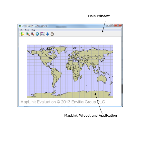
Starting the Application - Choosing a Framebuffer Configuration
For convenience, the sample uses Qt to create the OpenGL context that will be used by the drawing surface. Before this context is created, we want to suggest to Qt that it uses a framebuffer configuration with certain parameters. This happens inside main in main.cpp with the following code:
// Qt will be creating the OpenGL context for us. In order for the
// drawing surface to work at its best we ask it to choose a
// framebuffer configuration with a specific set of
// parameters.
QGLFormat f;
// Request a 24-bit depth buffer. A 16-bit depth buffer will also work.
f.setDepthBufferSize( 24 );
// Request a double-buffered configuration to eliminate flickering when
// moving around the map
f.setDoubleBuffer( true );
// Request 4x multisampling anti-aliasing if supported by the hardware
f.setSamples( 4 );
// Request an OpenGL 3.2 core profile context if supported by the hardware
f.setVersion( 3, 2 );
f.setProfile( QGLFormat::CoreProfile );
QGLFormat::setDefaultFormat( f );
Once we have done this, the main window for the application can be created and displayed.
If we were letting the drawing surface create its own OpenGL context then the above would not be needed as the drawing surface would internally select a suitable framebuffer configuration.
Initialisation
When the main window of the application is created, this creates the custom widget (the MapLink widget from maplinkwidget.cpp), which in turn creates the application class (from application.cpp). These objects get constructed in this order:
-
MainWindow
-
MapLinkWidget
-
Application
The MainWindow constructor only deals with installing event handlers for the toolbar button and menu entries - it doesn’t contain any interactions with MapLink.
Similarly, the majority of the MapLinkWidget constructor deals with ensuring event messages are propagated correctly to the widget. Additionally, it also instructs Qt to not clear the drawing area automatically before any drawing occurs as we use the MapLink drawing surface to do this.
The constructor of the Application class tells MapLink to load its configuration files from an installation on the host machine by calling TSLDrawingSurface::loadStandardConfig. This must be done before any MapLink functionality can be used - without it maps cannot be drawn at all. This setup only needs to be done once in the application - usually at start-up.
Creating the Drawing Surface
The next step is the creation of the drawing surface. Qt will call MapLinkWidget::initialiseGL inside maplinkwidget.cpp to ask the widget to perform any initial setup. The MapLink drawing surface doesn’t interface with Qt directly, it uses the underlying window handles from the operating system in order to allow it to be used with different application toolkits. Therefore, a small amount of platform specific code is needed in order extract these handles from Qt:
// Platform Specific Setup.
#ifdef X11_BUILD
# if QT_VERSION < 0x50100
// Extract the X11 information - QX11Info was removed in Qt5
QPlatformNativeInterface *native =
QGuiApplication::platformNativeInterface();
Display *display = static_cast<Display*>( native->nativeResourceForWindow(
"display", NULL ) );
Screen *screen = DefaultScreenOfDisplay(display);
#else
// Qt 5.1 introduced a different version of QX11Info for accessing widget native
// handles
int screenNum = DefaultScreen( QX11Info::display() );
Screen *screen = ScreenOfDisplay( QX11Info::display(), screenNum );
#endif
// pass to the application as we will need for the Drawing Surface
m_application->drawingInfo(display, screen);
#else
// The MapLink OpenGL drawing surface needs to know the window handle to
// attach to - query this from Qt
WId hWnd = winId();
// Pass the handle to the application so it can be used by the drawing
// surface
m_application->drawingInfo( hWnd );
#endif
These window handles are passed to the Application class for it to use when creating the drawing surface. The widget then calls Application::create in application.cpp to create the MapLink drawing surface and attach it to the window handles it just queried.
Creating the drawing surface requires another small amount of platform specific code - the exact type of drawing surface used depends on the platform the sample is being run on:
// Tell the drawing surface whether it will need to perform buffer swaps,
// or whether it is handled externally. See the constructor of
// MapLinkWidget.
TSLOpenGLSurfaceCreationParameters creationOptions;
creationOptions.swapBuffersManually( ML_QT_BUFFER_SWAP );
#ifdef X11_BUILD
// Get the active OpenGL context to attach the drawing surface to
GLXContext context = glXGetCurrentContext();
GLXDrawable drawable = glXGetCurrentDrawable();
// Create the Accelerated Surface object
m_drawingSurface = new TSLGLXSurface( m_display, m_screen, drawable,
context, creationOptions );
#else
HGLRC context = wglGetCurrentContext();
m_drawingSurface = new TSLWGLSurface( (HWND)m_window, false, context,
creationOptions );
#endif
if( !m_drawingSurface->context() )
{
// Error handling code
}
In both cases the application queries the active OpenGL context created by Qt and instantiates a MapLink drawing surface, telling it to attach itself to this context.
The TSLOpenGLSurfaceCreationParameters class can be used to control the behaviour of the MapLink drawing surface - in this case it’s used to tell the drawing surface not to perform buffer swaps after a draw as we have already told Qt that it should handle this.
Once the drawing surface is created, we check to make sure that the context method returns a valid value - if this returns NULL then the drawing surface did not attach successfully to the OpenGL context and cannot be used. The most common reason that this might occur is if the OpenGL implementation on the system does not meet the minimum requirements for the drawing surface.
Next, the application creates a data layer to load a map created by MapLink Studio into and adds this to the drawing surface so that its contents will be drawn when the drawing surface renders.
// Add a map data layer to the drawing surface
m_mapDataLayer = new TSLMapDataLayer();
// Set a cache size of 256Mb on the map layer to avoid reloading tiles
// from disk too frequently
m_mapDataLayer->cacheSize( 256 * 1024 );
m_drawingSurface->addDataLayer( m_mapDataLayer, m_mapLayerName );
At this stage the data layer is still empty, so nothing will be drawn yet.
The final step is the creation of the MapLink interaction mode manager and interaction modes.
// Now create and initialse the mode manager and modes
m_modeManager = new TSLInteractionModeManagerGeneric( this,
m_drawingSurface );
// Add the three interaction mode types to the manager - the zoom mode is
// the default
m_modeManager->addMode( new TSLInteractionModeZoom( ID_TOOLS_ZOOM ),
true ) ;
m_modeManager->addMode( new TSLInteractionModePan( ID_TOOLS_PAN ),
false ) ;
m_modeManager->addMode( new TSLInteractionModeGrab( ID_TOOLS_GRAB ),
false ) ;
// Display any errors that have occurred
const char *errorMsg = TSLErrorStack::errorString();
if( errorMsg )
{
// Error handling code
}
The interaction modes are a set of premade event handlers that implement some common methods of manipulating the view of a drawing surface based on user input. In this case we set the manager up to have zoom to rectangle, pan to point and grab and drag modes. The zoom to rectangle mode is set to be the default active interaction mode.
Handling Window Resizing
Although attached to the widget, the drawing surface is still not in a valid state for drawing as it has yet to be told how big the window to which it is attached is.
After MapLinkWidget::initializeGL has finished, Qt will immediately call MapLinkWidget::resizeGL in maplinkwidget.cpp. This call is forwarded to Application::resize in application.cpp, which updates both the drawing surface and the interaction mode manager with the size of the window they are drawing to.
if( m_drawingSurface )
{
// Inform the drawing surface of the new window size,
// attempting to keep the top left corner the same.
// Do not ask for an automatic redraw since we will get a call to
// redraw() to do so
m_drawingSurface->wndResize( 0, 0, width, height, false,
TSLResizeActionMaintainTopLeft ) ;
}
if( m_modeManager )
{
m_modeManager->onSize( width, height ) ;
}
Now that the drawing surface knows the window size, it is fully initialised and ready for drawing.
This same event sequence is used to handle changes to the window size while the application is running, as the drawing surface must be notified of any changes to the window to which it is attached.
Drawing to the Window
When the sample’s window needs to be redrawn, Qt will call MapLinkWidget::paintGL in maplinkwidget.cpp. This in turn calls Application::redraw in application.cpp to make the drawing surface draw all of the data layers inside it.
if( m_drawingSurface )
{
// Draw the map to the widget
m_drawingSurface->drawDU( 0, 0, m_widgetWidth, m_widgetHeight, true );
// Don't forget to draw any echo rectangle that may be active.
if ( m_modeManager )
{
m_modeManager->onDraw( 0, 0, m_widgetWidth, m_widgetHeight );
}
}
There is one data layer in the drawing surface - the TSLMapDataLayer we added inside the Application::create method. Currently this has no map loaded, so drawing will just clear the widget to the default background colour, which is white.
Loading a Map
When the Open Map toolbar button or menu item is selected, Qt invokes the registered event handler for this action, which is MainWindow::loadMap in mainwindow.cpp. This displays the operating system’s standard open dialog to let the user choose the map to load, and calls MapLinkWidget::loadMap in maplinkwidget.cpp to do the actual task of loading.
The widget does three things when loading a map:
-
Instructs the application class to load the map into its TSLMapDataLayer.
-
Tells the application to change the view of the drawing surface to cover the entirety of the new map, as the previous view of the drawing surface is unlikely to provide a useful view of the new map.
-
Asks Qt to redraw the window so that the new map can be seen, triggering the same call sequence as described in section 13.5.5.
The task of actually loading the data into the TSLMapDataLayer is done inside Application::loadMap in application.cpp.
if( !m_mapDataLayer->loadData( mapFilename.c_str() ) )
{
QMessageBox::critical( m_parentWidget, "Failed to load map",
mapFilename.c_str() );
return false;
}
if( m_modeManager )
{
// Loading a map invalidates any stored views in mode manager - this
// sample doesn't create any
m_modeManager->resetViews();
}
Changing the drawing surface view to cover the extent of the newly loaded map is done inside Application::resetView.
if( m_drawingSurface )
{
// Reset the drawing surface rotation as well
m_surfaceRotation = 0.0;
m_drawingSurface->rotate( m_surfaceRotation );
m_drawingSurface->reset( false );
}
The sample explicitly asks the drawing surface not to perform an immediate redraw as this is handled by MapLinkWidget. Any rotation that has been applied to the drawing surface by the sample is also removed.
Changing the View of the Map
Keyboard and mouse events that occur when the sample has focus are received by the MapLinkWidget in the *Event methods inside maplinkwidget.cpp. Each of these events is passed onto an equivalent event handler function inside the Application class in application.cpp. In turn, the Application class forwards these events to the MapLink interaction mode manager associated with the drawing surface. The manager will change the current view of the map based on the active interaction mode.
The return value of the interaction mode manager indicates to the Application class if a redraw is required based on the actions that have been taken. The Application passes this flag back to the MapLinkWidget as the return value from the event handler functions, which lets the MapLinkWidget trigger a redraw of the window when needed.
Changing the Active Interaction Mode
When the sample is started, the zoom to rectangle mode is the default interaction mode. This can be changed through the toolbar buttons or corresponding menu items, which invoke the registered action handlers in the MainWindow These actions are forwarded on to the MapLinkWidget, which in turn forwards them on to the Application.
The Application instructs the interaction mode manager to change the interaction mode using the unique identifiers assigned to each the interaction modes when they were initially added to the interaction mode manager when it was created.
void Application::activatePanMode()
{
// Activate the pan interaction mode
if( m_modeManager )
{
m_modeManager->setCurrentMode( ID_TOOLS_PAN ) ;
}
}
void Application::activateZoomMode()
{
// Activate the zoom interaction mode
if( m_modeManager )
{
m_modeManager->setCurrentMode( ID_TOOLS_ZOOM ) ;
}
}
void Application::activateGrabMode()
{
// Activate the grab interaction mode
if( m_modeManager )
{
m_modeManager->setCurrentMode( ID_TOOLS_GRAB ) ;
}
}
Additional Data Layers for the OpenGL Surface
When using the OpenGL drawing surface applications can use an additional data layer called the TSLStaticMapDataLayer. This data layer is an alternative to the TSLMapDataLayer that does not support the more advanced features of the TSLMapDataLayer, but in return offers significantly higher drawing performance.
The TSLStaticMapDataLayer lacks the following features of the TSLMapDataLayer:
-
Runtime projection
-
Flashback
-
Support for dynamic renderers
-
Persistent tile caches
If any of these features are required in an application then the TSLMapDataLayer should be used, otherwise the TSLStaticMapDataLayer may be more suitable.
The API of the TSLStaticMapDataLayer is almost identical to that of the TSLMapDataLayer so it is simple for an application to switch them as desired. The primary difference between the two data layers is in the methods that control each layer’s cache (cacheSize and clearCache). In the TSLStaticMapDataLayer this is split into two different sets of methods, one used for drawing and one used for querying (such as the findEntity or query methods).
In addition to allowing for finer control over the memory use of the layer, the split allows for more flexible use of the data layer. Unlike the TSLMapDataLayer, with the TSLStaticMapDataLayer an application may retain the results of a query operation while the layer is redrawn as the separate caches mean changes to the drawing cache do not affect the objects returned by a query. It is also possible to use the data layer query methods on the TSLStaticMapDataLayer from a different thread to the one that the layer is drawn in, provided the application takes care to ensure that methods that would trigger a clearing of both caches (e.g. loadData) are not called without synchronisation inside the application. Issuing queries from more than one thread against the same data layer is not supported.
The Drawing Surface Coordinate System and Custom Data Layers
Separate from the coordinate system used for coordinate transformations in the drawing surface and data layers via a TSLCoordinateSystem object, the OpenGL drawing surface defines a different coordinate system that is used to map the OpenGL coordinate space to the screen. When all rendering is performed through MapLink data layers and the TSLRenderingInterface an application doesn’t need to understand this coordinate space - it is all taken care of internally. However, when the application performs its own OpenGL rendering via a TSLCustomDataLayer or after MapLink has finished drawing it is important to understand how to correctly position items relative to the map.
The OpenGL drawing surface defines this rendering coordinate space to be the TMC extent of the area being rendered, without any drawing surface rotation or dynamic arc scaling included, centred on 0,0 (centre of the screen). The TMC extent that this equates to from the active TSLCoordinateSystem can be determined if required as follows, although it is generally not needed:
TSLDrawingSurface *surface = ...
TSLEnvelope renderExtent;
surface->getTMCExtent(renderExtent);
if(surface->getOption(TSLOptionDynamicArcSupportEnabled))
{
// Dynamic arc is enabled, remove any scaling effect applied
// to the envelope
double tmcPerDUX = 0.0, tmcPerDUY = 0.0;
surface->TMCperDU(tmcPerDUX, tmcPerDUY);
renderExtent.scale(tmcPerDUY / tmcPerDUX, 1.0);
}
// renderExtent now contains the TMC extent of the surface's drawing
// coordinate system in the active TSLCoordinateSystem of the drawing
// surface
As mentioned above, this extent is centred on 0,0 when mapped to the drawing surface’s rendering coordinate system (i.e., the bottom left of the envelope is equal to -width()/2, -height/2 and the top right of the envelope is equal to width()/2. height()/2). The bottom left and top right of this envelope map to the bottom left and top right of the screen - therefore 0,0 in the rendering coordinate system always maps to the centre of the screen.
Positioning Items in Practice
Like all OpenGL applications, the OpenGL drawing surface uses matrices to describe the transformations to perform when rendering items to the screen. These are divided into two matrices - the modelview matrix which describes any transformations to be applied within the rendering coordinate system, and the projection matrix which maps the results of this to a form OpenGL can interpret.
The drawing surface provides access to its matrices for the current or previous draw via the modelViewMatrix and projectionMatrix methods on TSLOpenGLDrawingSurface. The modelview matrix will already contain any drawing surface rotation or dynamic arc scaling that apply for the draw. Additionally, for convenience it also provides access to the TMC position that maps to 0,0 in rendering space via the coordinateCentreX and coordinateCentreY methods. Note that the centre coordinates are returned as doubles - they may not necessarily map to integer coordinate space.
The combination of these items allows for the construction of a modelview matrix that will correctly locate an item being drawn relative to the map. Generally, object drawn via OpenGL are object centred - i.e. their coordinates are defined relative to an origin local to that object rather than relative to the active coordinate system. Since coordinates in OpenGL must be provided in 32bit floats in most cases this is particularly important due to precision - the MapLink TMC coordinate space uses 32bits of integer precision but 32bit floats only provide 24bits of integer precision. By Object-centring and translating to the correct location during a draw the problem of jittery movement of objects when operating near the edges of MapLink’s TMC space does not occur.
Putting this all together, the code for positioning an object centred item for drawing inside a TSLCustomDataLayer might look like the following:
bool MyCustomLayer::drawLayer(TSLRenderingInterface *renderingInterface, const TSLEnvelope* extent, TSLCustomDataLayerHandler& layerHandler)
{
TSLOpenGLSurface *surface = reinterpret_cast<TSLOpenGLSurface*>(
layerHandler.drawingSurface());
// This contains the TMC location of the centre of the object
// in the drawing surface's active coordinate system
TSLCoord objectTMCPosition = calculateObjectPosition();
// Determine the modelview matrix to position the object
// in the right place relative to the current drawing.
Matrix modelViewMat(surface->modelViewMatrix());
modelViewMat.translate(objectTMCPosition.x() --
surface->coordinateCentreX(),
objectTMCPosition.y() --
surface->coordinateCentreY());
if(removeDynamicArcScaling)
{
// This will remove the effect of dynamic arc (if active)
// from any subsequent transformations.
double tmcPerDUX = 0.0, tmcPerDUY = 0.0;
surface->TMCperDU(tmcPerDUX, tmcPerDUY);
modelViewMat.scale(tmcPerDUX / tmcPerDUY, 1.0);
}
// Upload the matrices to OpenGL
surface->stateTracker()->useProgram(m_program);
glUniformMatrix4fv( m_modelViewUniform, 1, GL_FALSE,
modelViewMat.matrix());
glUniformMatrix4fv( m_projectionUniform, 1, GL_FALSE,
surface->projectionMatrix());
// Now draw the object
...
return true;
}
Interspersing Custom Rendering with MapLink Rendering
The OpenGL drawing surface will internally change the order or defer drawing for performance reasons, using OpenGL’s depth buffer to ensure items appear in the correct order on screen. When all rendering inside a custom data layer is performed by MapLink or implemented by the application there is no problem, and everything will work as expected. However, when mixing both MapLink rendering and custom rendering within the same data layer application drawn items may not necessarily appear in the expected order relative to the items drawn through MapLink.
In the simple case where all of the application rendering in the data layer occurs after all MapLink rendering, the application can use the flushPendingDraws method on TSLOpenGLSurface to ensure all MapLink draw commands have been sent to the GPU command stream before beginning application rendering. This might look as follows:
bool MyCustomLayer::drawLayer(TSLRenderingInterface *renderingInterface, const TSLEnvelope* extent, TSLCustomDataLayerHandler& layerHandler)
{
TSLOpenGLSurface *surface = reinterpret_cast<TSLOpenGLSurface*>(
layerHandler.drawingSurface());
// This function performs rendering through the rendering interface
doMapLinkDrawing(renderingInterface);
// Ensure all MapLink rendering is done before we continue
surface->flushPendingDraws();
// Custom application rendering in this case does not use the
// depth buffer
surface->stateTracker()->disableDepthTest();
// Custom application rendering occurs in here
doMyCustomRendering();
surface->stateTracker()->enableDepthTest();
return true;
}
If the custom rendering is mixed in with MapLink rendering, then it can often be beneficial to make use of the depth buffer to ensure ordering in the same way that the drawing surface does. To assist in this the TSLOpenGLSurface provides the acquireDepthSlice method which can be used to reserve one or more depth buffer values for custom rendering use. The value returned is the depth in OpenGL’s normalised device coordinate space, which since the OpenGL drawing surface uses an orthographic 2D projection and so has no perspective division is also OpenGL’s clip space. The value can therefore be assigned directly to either gl_FragDepth in the application’s fragment shader or to gl_Position.z in the application’s vertex shader.
In the following examples depthValue is the value obtained from calling acquireDepthSlice:
// Vertex shader example - this method can be used on OpenGL ES 2.0 systems
// where gl_FragDepth is not available
#version 150 core
uniform float depthValue;
uniform mat4 modelViewMatrix;
uniform mat4 projectionMatrix;
in vec2 vertexPosition;
void main()
{
gl_Position = (projectionMatrix * modelViewMatrix) * vec4( vertexPosition,
0.0, 1.0 );
gl_Position.z = depthValue;
}
// Fragment shader example
#version 150 core
uniform vec4 colour;
uniform float depthValue;
out vec4 pixelColour;
void main()
{
gl_FragDepth = depthValue;
pixelColour = colour;
}
When using the depth buffer in this fashion it is not necessary to call flushPendingDraws in order to ensure correct ordering. Depth buffer values obtained in this fashion only apply to the current data layer being drawn as the depth buffer will be cleared when drawing each data layer.
Transparency
In addition to per-layer transparency, the OpenGL drawing surface also allows for per-entity transparency via the TSLRenderingAttributeEdgeOpacity, TSLRenderingAttributeExteriorEdgeOpacity, TSLRenderingAttributeFillOpacity, TSLRenderingAttributeTextOpacity and TSLRenderingAttributeSymbolOpacity rendering attributes.
When using per-entity transparency, correct visualisation requires that strict back-to-front rendering order is used, however for performance reasons MapLink may internally rearrange the order items are drawn in. This may sometimes lead to the following situation:
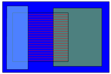
This image contains four rectangles in the following order:
-
An opaque blue rectangle with black opaque edges.
-
A partially transparent green rectangle with black opaque edges.
-
A red rectangle with a patterned fill style with black opaque edges.
-
A partially transparent cyan rectangle with black opaque edges.
With this ordering, the patterned red rectangle should be visible through the partially transparent cyan rectangle, however after reordering the rectangles were drawn in this order:
-
The black opaque edges for all four rectangles.
-
The opaque blue rectangle fill.
-
The partially transparent green rectangle fill.
-
The partially transparent cyan rectangle fill.
-
The patterned red rectangle fill.
When drawn in this order, the section of the patterned red rectangle that should be visible through the partially transparent cyan rectangle has not been drawn at the point the cyan rectangle is rendered, so this rectangle’s colour was blended with the opaque blue rectangle instead of the patterned red rectangle. Effectively it was drawn as if the patterned red rectangle did not exist. When the patterned red rectangle is drawn at the end, the section covered by the partially transparent cyan rectangle does not get drawn again as it is considered to already be obscured by an object in front (the cyan rectangle).
MapLink attempts to minimise the situations where this might occur. Specifically, it can only occur when the following conditions are true:
-
Rendering that occurs within the same MapLink data layer.
-
For data layers that contain multiple tiles (e.g. a TSLMapDataLayer), rendering that occurs within the same tile.
-
Rendering that occurs at the same render level.
-
Rendering that occurs at the same rendering pass (for multi-pass linestyles).
-
The overlapping transparent items use different fill or line styles, or are different types of rendering (e.g. a polygon’s fill and a polygon’s edge).
-
The item being drawn is not a TSLSymbol.
MapLink will attempt to ensure that opaque geometry is drawn before any transparent geometry where possible, but does not provide any guarantees of the order that transparent geometry will be drawn in by default. For situations where the consistently correct display of overlapping transparent objects is important and the transparent geometry cannot be put in a separate render level, the drawing surface allows an application to hint at the required level of correctness through the TSLOpenGLTransparencyHintEnum enumeration.
This enumeration lets an application specify the following hints about how it uses transparency on a per-data layer basis, ordered from fastest to slowest:
-
TSLOpenGLTransparencyHintNever - MapLink will attempt to draw opaque geometry before transparent geometry where doing so will not cause a significant performance impact. Opaque geometry may be drawn in any order. The rendering order of transparent geometry is not guaranteed.
-
TSLOpenGLTransparencyHintFlushOpaque - Any pending opaque geometry not yet rendered will be drawn when a transparent item is encountered. Opaque geometry may be drawn in any order. Transparent items are drawn in order. The performance impact of this setting depends on the number of transparent items in the data layer.
-
TSLOpenGLTransparencyHintAlways - No draw reordering occurs - all items are drawn in order from back to front. This setting has a substantial performance impact that increases with the number of items drawn.
In almost all cases using TSLOpenGLTransparencyHintNever or TSLOpenGLTransparencyHintFlushOpaque is sufficient to give acceptable output - TSLOpenGLTransparencyHintAlways should only be used as a last resort due to its performance impact.
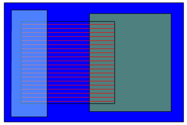
Going back to the example at the beginning of this section, the same geometry drawn using the TSLOpenGLTransparencyHintFlushOpaque hint will be rendered in the expected order, giving this output:
For systems using OpenGL ES 2.0 or OpenGL 3.1 or earlier, entities using a patterned fill or line style count as transparent for the purposes of draw ordering. On these systems items that would be visible through the pattern will not be shown if they are drawn after the patterned item. When using a system supporting OpenGL 3.2 or later MapLink uses alpha testing for rendering these items and thus they count as opaque geometry for the purposes of draw ordering unless the entity has also been set as transparent via its rendering attributes.
Anti-aliasing
The OpenGL drawing surface can use two different types of anti-aliasing to reduce the visibility of jagged edges on vector features. These are multisampling, which uses features provided by the graphics hardware, and a post-processing implementation that can be used when multisampling is not supported.
Multisampling
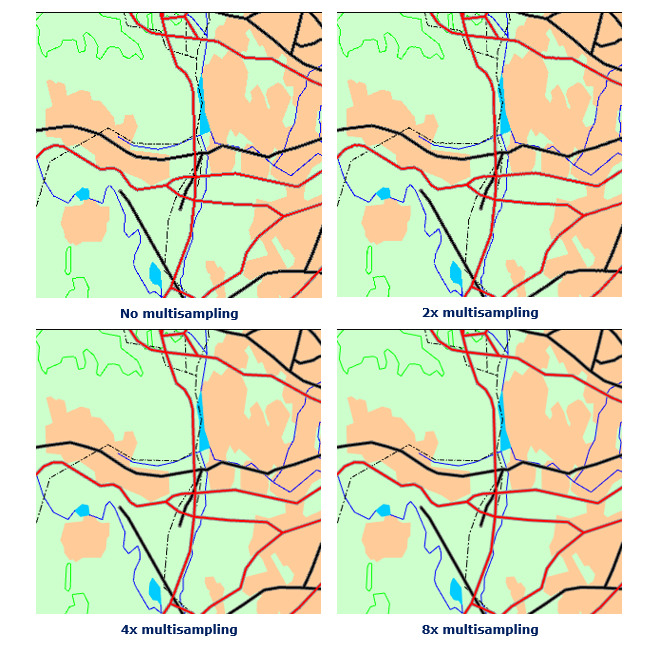
Multisampling can be enabled when creating the drawing surface using one of the constructors that internally create an OpenGL context using the numMultisampleSamples option of the TSLOpenGLSurfaceCreationParameters class. The drawing surface will attempt to locate a configuration supported by the graphics hardware that supports the requested level of multisampling, but if none exists will use the highest level available on the hardware. Higher levels provide better image quality at the cost of lower performance, but modern hardware can generally run with 4x or higher multisampling without trouble.
The specific levels of multisampling available depend on the graphics hardware in the system.
The images shown on the next page illustrate the effect of increasing levels of multisampling on image quality:
The decision on whether to use multisampling must be made at the time the drawing surface is created - it cannot be enabled or disabled on an existing drawing surface.
On embedded and mobile systems using OpenGL ES 2.0 multisampling will not be applied to any buffered or transparent layers (layers using the TSLPropertyBuffered or TSLPropertyTransparency data layer properties). On systems that do not support OpenGL 3.2 the ARB_texture_multisample extension is required.
Post-processing Anti-aliasing
When the graphics hardware supports multisampling there is little reason to use post-processing anti-aliasing as multisampling provides better image quality, but if multisampling is not supported then it can be better than no anti-aliasing.
Unlike multisampling, post-processing anti-aliasing can be enabled and disabled at runtime via the TSLOpenGLSurface::setAntialiasingMode method as long as the drawing surface was not created with multisampling enabled - multisamping and post-processing anti-aliasing cannot be used at the same time.
Post-processing anti-aliasing has two available settings - FXAAStrong and FXAAWeak. The strong setting will remove most jagged edges but will display noticeable visual artefacts on single pixel thickness features. The weak setting will sometimes leave noticeable jagged edges but does not generate artefacts around single pixel features as the strong setting does.
The images below demonstrate the effect of these settings on image quality:
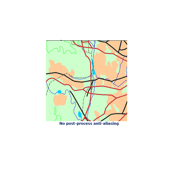
When configuring feature rendering for maps and overlaps that is intended to be used with the post-process anti-aliasing strong setting it is generally better to avoid using any single pixel wide features entirely. Instead configure these features to be two pixels wide and possibly use a slightly lighter colour if the feature may be in areas of high contrast (e.g. black lines against pale backgrounds). The anti-aliasing effect softens the lines so that the extra width is not as pronounced and often provides better quality than using the weak setting with single pixel thick features due to the reduced aliasing.
Hardware-Supported Raster Formats
Modern graphics hardware supports a number of specialized raster formats (normally referred to as ‘compressed textures’) that are highly efficient for drawing. These formats are both faster to load and use less memory than other more traditional raster formats such as JPEG and PNG as they do not need to be decompressed before drawing.
In order to allow applications to take advantage of these formats, the TSLOpenGLDataOptimiser utility class provides means for an application to convert any supported raster format into one of the special hardware-supported formats at runtime. These converted rasters can then be loaded as normal into data layers such as the TSLRasterDataLayer as with any other raster format.
When displaying very high resolution imagery it is advisable to first generate a raster pyramid from the source raster as described in section 12.8.3 before converting the raster using the TSLOpenGLDataOptimiser. Graphics hardware is limited in the maximum resolution of raster that can be displayed (from 2048x2048 on some mobiles and embedded devices; up to 16384x16384 on recent desktop hardware), so creating raster pyramids is necessary to display images that are larger than what is supported by the hardware the application is running on.
Maps created by MapLink Studio that contain rasters can also take advantage of these specialised raster formats when the map is used with the OpenGL drawing surface. This can be done either at the time the map is created by MapLink Studio (refer to the MapLink Studio User Guide for details), or for existing maps through the TSLOpenGLDataOptimiser. At runtime MapLink will only attempt to load the image format(s) that are supported by the hardware, so it is not necessary to prepare a version of each map for each image format.
Integrating with Other OpenGL Applications
It is sometimes desirable to use the OpenGL drawing surface in conjunction with user interface toolkits or other libraries that perform their own OpenGL context creation and management. For this situation each of the window system interface classes provides a constructor that accepts an existing OpenGL context that the drawing surface should use instead of creating its own.
When creating the drawing surface in this way an application usually wants to set the swapBuffersManually option from the TSLOpenGLSurfaceCreationParameters used to false as buffer swaps are usually managed by the same code that creates the OpenGL context.
To prevent the drawing surface from clearing the colour buffer during a draw, set the clear argument passed to TSLDrawingSurface::drawDU or TSLDrawingSurface::drawUU to false. This option only inhibits clearing of the colour buffer - the depth buffer and stencil buffer (if present) will still be cleared by the drawing surface.
When changing OpenGL state an application should normally use the drawing surface’s TSLOpenGLStateTracker object if it provides a function that maps to the state being changed. The drawing surface internally tracks the current OpenGL state in order to remove redundant state changes being sent to the driver which can affect performance; thus it must be kept up to date with the actual OpenGL state in order to function correctly. The initial values of the state tracker are read from OpenGL on drawing surface creation. If the state of any settings that the state tracker stores are modified outside of the state tracker the application should use the reset method to force it to re-read the current OpenGL state.
Suggested Framebuffer Configurations
When the OpenGL drawing surface does not create an OpenGL context, it is up to the application to ensure the framebuffer configuration used is suitable for use with the drawing surface. The requirements for the drawing surface are as follows:
-
An RGBA framebuffer (GLX_RENDER_TYPE is GLX_RGBA_BIT, WGL_PIXEL_TYPE_ARB is WGL_TYPE_RGBA_ARB or EGL_COLOR_BUFFER_TYPE is EGL_RGB_BUFFER).
-
A depth buffer of 16 bits or greater.
- On OpenGL ES 2.0 systems EGL_RENDERABLE_TYPE must be EGL_OPENGL_ES2_BIT.
Any other settings may be freely chosen by the application.
The TSLGLXSurface and TSLNativeEGLSurface provide convenience utility methods, named preferredVisualID and preferredConfigID, that can be used to identify the framebuffer configuration that the drawing surface would prefer to use.
Off-screen Rendering
There are two main scenarios for wanting to make the OpenGL drawing surface render to an off-screen surface:
-
To take a frame of output from a drawing surface that normally draws to a window and save it for reuse, such as when rendering an overview of a map to a texture.
-
To have a drawing surface that is not attached to a window and always draws off-screen.
Almost no graphics drivers allow for hardware acceleration when rendering to a bitmap or pixmap, therefore the OpenGL drawing surface cannot be attached to one of these for off-screen rendering. Instead, OpenGL itself must be used to accomplish this.
The process for the first type of off-screen rendering is consistent across the various window system interface classes as it only uses standard OpenGL functionality - framebuffer objects, generally referred to as FBOs.
The second type of off-screen rendering affects how the OpenGL context must be created, and thus the specifics differ between Windows, X11 and EGL based systems.
Redirecting Drawing Surface Output to a Framebuffer Object
The OpenGL drawing surface respects any framebuffer object (FBO) bound at the point that it starts drawing and will redirect its output to the buffers bound to this FBO. Therefore making the drawing surface render to a texture or renderbuffer is as simple as binding the desired FBO before calling drawDU or drawUU on the drawing surface. The code to create this FBO would look as follows:
// m_surface is a TSLOpenGLSurface that is attached to a window as
// normal for on-screen rendering.
// Creates the framebuffer object and attachments to use for offscreen
// rendering
bool createFBO()
{
TSLDeviceUnits surfaceX1 = 0, surfaceY1 = 0,
surfaceX2 = 0, surfaceY2 = 0;
m_surface->getDUExtent( &surfaceX1, &surfaceY1,
&surfaceX2, &surfaceY2 );
glGenFramebuffers( 1, &m_fbo );
glGenTextures( 1, &m_texture );
glGenRenderbuffers( 1, &m_depthBuffer );
// Initialise the colour texture and depth render buffer to
// match the drawing surface's size
m_surface->stateTracker()->bindTexture( GL_TEXTURE0, GL_TEXTURE_2D,
m_texture );
glTexParameteri( GL_TEXTURE_2D, GL_TEXTURE_MIN_FILTER, GL_NEAREST );
glTexParameteri( GL_TEXTURE_2D, GL_TEXTURE_MAG_FILTER, GL_NEAREST );
glTexParameteri( GL_TEXTURE_2D, GL_TEXTURE_WRAP_S, GL_CLAMP_TO_EDGE );
glTexParameteri( GL_TEXTURE_2D, GL_TEXTURE_WRAP_T, GL_CLAMP_TO_EDGE );
glTexImage2D( GL_TEXTURE_2D, 0, GL_RGBA8, surfaceX2-surfaceX1,
surfaceY2-surfaceY1, 0, GL_RGBA, GL_UNSIGNED_BYTE,
NULL );
glBindRenderbuffer( GL_RENDERBUFFER, m_depthBuffer );
glRenderbufferStorage( GL_RENDERBUFFER, GL_DEPTH_COMPONENT24,
surfaceX2-surfaceX1, surfaceY2-surfaceY1 );
// Make the fbo the active render target
m_surface->stateTracker()->bindFramebuffer( GL_FRAMEBUFFER, m_fbo );
glFramebufferTexture2D( GL_FRAMEBUFFER, GL_COLOR_ATTACHMENT0,
GL_TEXTURE_2D, m_texture, 0 );
glFramebufferRenderbuffer( GL_FRAMEBUFFER, GL_DEPTH_ATTACHMENT,
GL_RENDERBUFFER, m_depthBuffer );
// Make sure we created the fbo correctly
GLenum status = glCheckFramebufferStatus( GL_FRAMEBUFFER );
switch( status )
{
case GL_FRAMEBUFFER_COMPLETE:
m_surface->stateTracker()->bindFramebuffer( GL_FRAMEBUFFER, 0 );
// Everything worked - we are done
return true;
default:
// An error occurred - the created objects should be deleted here
...
return false;
}
}
To make the drawing surface draw to the texture the applications draw function might look as follows:
// m_surface is a TSLOpenGLSurface that is attached to a window as
// normal for on-screen rendering.
//
// m_fbo is the framebuffer object already created
void draw( int width, int height, bool drawOffscreen )
{
if( drawOffscreen )
{
m_surface->stateTracker()->bindFramebuffer( GL_FRAMEBUFFER, m_fbo );
// Drawing will go to the buffers attached to the FBO - in this
// case the texture created earlier.
m_surface->drawDU( 0, 0, width, height, true );
}
else
{
m_surface->stateTracker()->bindFramebuffer( GL_FRAMEBUFFER, 0 );
// Drawing will go to the window the surface is attached to
m_surface->drawDU( 0, 0, width, height, true );
}
}
After the draw completes the texture will then contain the output from the drawing surface.
Windowless Drawing Through GLX with the TSLGLXSurface
GLX allows an OpenGL context to be created from a GLXPbuffer instead of a Window XID. These are created through glXCreatePbuffer which returns the GLXDrawable needed to create the OpenGL context, which the drawing surface can then be attached to. When using GLXPbuffers the application must create the OpenGL context itself. An example of this is below:
int configAttribs[] = { GLX_DOUBLEBUFFER, False,
GLX_DEPTH_SIZE, 16,
GLX_DRAWABLE_TYPE, GLX_PBUFFER_BIT,
GLX_RENDER_TYPE, GLX_RGBA_BIT,
GLX_CONFIG_CAVEAT, GLX_NONE,
None };
int numConfigMatches = 0;
GLXFBConfig *configs = glXChooseFBConfig( m_display, m_screenNum,
configAttribs,
&numConfigMatches );
if( !configs || numConfigMatches == 0 )
{
// Error - no valid framebuffer configurations
...
}
int bufferAttribs[] = { GLX_PBUFFER_WIDTH, width,
GLX_PBUFFER_HEIGHT, height,
None };
GLXPbuffer glxDrawable = glXCreatePbuffer( m_display, configs[0],
bufferAttribs );
// This code assumes support for GLX_ARB_create_context
int contextAttribs[] = { GLX_CONTEXT_MAJOR_VERSION_ARB, 3,
GLX_CONTEXT_MINOR_VERSION_ARB, 2,
GLX_CONTEXT_PROFILE_MASK_ARB,
GLX_CONTEXT_CORE_PROFILE_BIT_ARB
GLX_RENDER_TYPE, GLX_RGBA_TYPE,
None };
GLXContext context = glXCreateContextAttribs( m_display, configs[0], None,
True, contextAttribs);
if( !glXMakeContextCurrent( m_display, glxDrawable, glxDrawable,
context ) )
{
// Error - cannot activate context
...
}
// Attach the drawing surface to the OpenGL context
TSLOpenGLSurfaceCreationParameters creationOptions;
creationOptions.useVSync( false );
creationOptions.swapBuffersManually( true );
TSLGLXSurface *surface = new TSLGLXSurface( m_display, m_screen,
glxDrawable, context,
creationOptions );
XFree( configs );
Windowless Drawing Through EGL with the TSLEGLSurface
Windowless rendering with EGL is very similar to GLX - an OpenGL context can be created from an EGLSurface tied to a Pbuffer instead of an EGLNativeWindowType. When using EGL Pbuffers the application must create the OpenGL context itself. An example of this is below:
EGLint configAttribs[] = { EGL_RENDERABLE_TYPE, EGL_OPENGL_ES2_BIT,
EGL_COLOR_BUFFER_TYPE, EGL_RGB_BUFFER,,
EGL_SURFACE_TYPE, EGL_PBUFFER_BIT,
EGL_DEPTH_SIZE, 16,
EGL_SAMPLES, 0,
EGL_NONE };
EGLint numConfigMatches = 0;
EGLConfig config;
if( !eglChooseConfig( m_display, configAttribs, &config, 1,
&numConfigMatches ) || numConfigMatches == 0 )
{
// Error - no valid framebuffer configurations
...
}
EGLint bufferAttribs[] = { EGL_WIDTH, width,
EGL_HEIGHT, height,
EGL_NONE };
EGLsurface eglSurface = eglCreatePbufferSurface( m_display, config
bufferAttribs );
EGLint contextAttribs[] = { EGL_CONTEXT_CLIENT_VERSION, 2,
EGL_NONE };
EGLContext context = eglCreateContext ( m_display, config, EGL_NO_CONTEXT,
contextAttribs );
if( !eglMakeCurrent( m_display, eglSurface, eglSurface, context ) )
{
// Error - cannot activate context
...
}
// Attach the drawing surface to the OpenGL context
TSLEGLSurface *surface = new TSLEGLSurface();
surface->attach();
Windowless Drawing on Windows with the TSLWGLSurface
Windowless drawing on Windows is not possible - while WGL has the same pbuffer concept as GLX and WGL through the WGL_ARB_pbuffer OpenGL extension, because it is an OpenGL extension the functions necessary to use it require an active OpenGL context - thus giving a circular dependency of requiring an OpenGL context in order to create an OpenGL context.
The standard method of dealing with this situation is to create an invisible window to create the OpenGL context from, and use the FBO method described in section 13.12.1. Applications should not render to the invisible window as this is undefined behaviour in OpenGL and so may not work on all graphics hardware.
Threading
An OpenGL context can only be active in one thread at a time, and each thread can only have one context active. This means that drawing can only occur in the thread associated with its context and attempting to call any functions that result in drawing in another thread will result in errors being generated and no drawing occurring.
The thread the drawing surface’s context is bound to can be changed by calling the makeContextCurrent function available on each of the window system interface classes from the new thread, however this is an expensive operation so applications should avoid frequently migrating a drawing surface between threads.
Drawing data layers and entities in the OpenGL drawing surface creates GPU resources than MapLink associates with the item being drawn. These resources must be freed in the same thread as the OpenGL context that they were created from in order to avoid resource leaks. This can be done either by deleting the object in this thread or using the releaseResources method on the TSLDataLayer or TSLEntity.
A multithreaded application should generally assign one rendering thread to each OpenGL context (and thus drawing surface) used, with other application logic occurring other threads. Guidelines on using MapLink in a threaded environment can be found in section 28.
Performance Tips
There are several important considerations when writing an application using the OpenGL drawing surface in order to achieve maximum performance. This section contains suggestions on how to approach various tasks in the most performant way with the OpenGL drawing surface and lists some common pitfalls to avoid.
General Tips
The first time an item is drawn the OpenGL drawing surface will perform a set of processing tasks necessary in order to create the necessary GPU resources to draw the item. The results of this processing are associated with the item so that they can be reused in subsequent draws. For complex items this calculation can take a noticeable amount of time and so an application should try and avoid situations that cause this calculation to be redone unnecessarily. The situations that can trigger this recalculation are as follows:
Removing a TSLDataLayer from the drawing surface will delete any associated GPU resources. Re-adding the data layer to the surface will trigger the processing task for the data layer on the next draw. Applications should avoid removing and re-adding data layers to the surface as a method of controlling layer visibility - the TSLPropertyVisible data layer property should be used for this task.
Calling notifyChanged on a TSLDataLayer indicates to the drawing surface that the any existing resources need to be recreated due to the underlying data of the data layer changing in a way it cannot detect. In most cases the drawing surface can identify when the data layer has been modified in a way that requires recalculation (such as loading a new map into a TSLMapDataLayer or modifying the contents of a TSLEntitySet), so applications should only call notifyChanged in situations where this will not occur automatically.
Modifying a TSLEntity by changing its coordinates, or in the case of a TSLEntitySet adding/removing entities from the set invalidates the GPU resources for all entities in the controlling data layer or entity set. The OpenGL drawing surface offers per-data layer controls for applications to provide hints on how GPU resources should be created for TSLEntities in order to minimise the amount of recalculations that occur - see section 13.14.2 for details.
Each transparent data layer in a draw uses an additional amount of graphics memory equal to that used by the default framebuffer of the drawing surface. Applications should avoid large numbers of transparent layers on graphics hardware with low amounts of memory.
Applications should use the drawing surface’s TSLOpenGLStateTracker to modify the OpenGL state where possible instead of using its reset method to force it to re-read the OpenGL state. Re-reading the OpenGL state will normally cause the thread containing the OpenGL context to block until all pending OpenGL commands are complete which can cause stalls during application rendering.
Data layers shared between multiple OpenGL drawing surfaces do not share GPU resources even if their OpenGL contexts share resource lists. Therefore, a data layer in two OpenGL drawing surfaces requires twice as much graphics memory as the same data layer in one drawing surface.
Increasing the cache size of a TSLDataLayer will increase the amount of GPU memory used accordingly. Applications should try to avoid setting large cache sizes on systems that have low amounts of GPU memory.
Other documentation may refer to performance differences between cosmetic and geometric pens when drawing lines. The OpenGL drawing surface has no distinction between these types and therefore there is no performance difference between then.
Vector Geometry in Data Layers
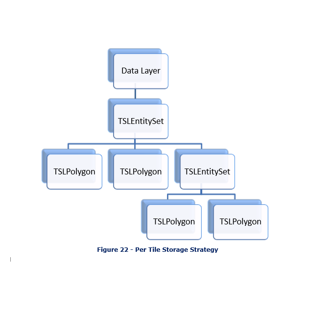
By default, data layers containing vector geometry (i.e. TSLEntities) have one combined GPU resource created for all entities within a single tile of that layer, or one resource for that layer for layers that are not tiled.
When using layers providing user-editable TSLEntities, such as the TSLStandardDataLayer this can be problematic since changing any single TSLEntity requires reprocessing the entire tile or entity set. For this situation the OpenGL drawing surface allows an application to provide a hint about how it should structure GPU resources to avoid unnecessary recalculation through the TSLOpenGLStorageStrategyEnum enum and setLayerStorageStrategy method on TSLOpenGLDrawingSurface. This allows an application to structure its data into a series of self-contained resource groups that are modified together.
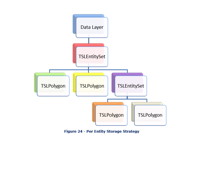
The diagrams below show a simple entity hierarchy using each of the storage strategies. The background colour of each item denotes the resource group it belongs to, with items having the same background colour being in the same group.
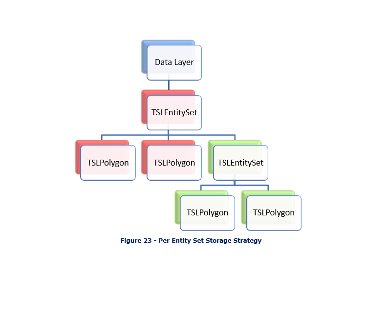
If an application had two types of vector geometry in a TSLStandardDataLayer, one that was rarely modified and one that was frequently modified, these could be stored in two different TSLEntitySets on the TSLStandardDataLayer, with the layer’s storage strategy set to TSLOpenGLPerEntitySetStrategy. This way, modifying the contents of one entity set would not invalidate the GPU resources of the other entity set leading to improved performance.
Applications should avoid creating many small resource groups in this fashion as each additional group requires additional OpenGL state changes to draw and reduces the ability for the drawing surface to reorder drawing for best performance. For the same reason an application should avoid using the TSLOpenGLPerEntityStrategy unless absolutely necessary.
Using the move, rotate, rotation, scale, scaleXY and translate methods on TSLEntity, or modifying the rendering attributes of the TSLEntity does not trigger the invalidation of GPU resources for the resource group.
Using the TSLRenderingInterface
Applications should avoid using drawPolygon and drawPolyline on the TSLRenderingInterface in conjunction with the OpenGL drawing surface. These methods require the drawing surface to create and delete the necessary resources to draw the geometry every time the method is called, which leads to increasingly poor performance the more these methods are called in a frame.
Instead, an application should set the layer storage strategy on the drawing surface for the data layer to TSLOpenGLPerEntitySetStrategy and create a persistent TSLEntitySet that contains TSLPolygons and TSLPolylines for each of the items that need to be drawn. The application should draw these items by passing the containing TSLEntitySet to the drawEntity function on the TSLRenderingInterface. This allows the drawing surface to avoid having to perform the same set of calculations every frame for this geometry.
For the same reasons an application should not recreate any TSLEntities that will be used for drawing each frame - these should be persisted between frames where possible.
Any entities used with the TSLRenderingInterface in this fashion must have the releaseResources method called from the application’s drawing thread before the drawing surface is destroyed or detached.
Dynamic Renderers
Dynamic renderers used with the OpenGL drawing surface should avoid calling drawPolygon and drawPolyline on the TSLRenderingInterface as described in section 13.14.3. When using a dynamic renderer to draw an entity with custom rendering attributes the renderer should always return TSLDynamicRendererActionUseCurrentRendering from the render method and allow MapLink to draw the entity. Dynamic renderers implemented this way will perform substantially faster when used with the OpenGL drawing surface.
Raster Data in Data Layers
Raster drawing is normally fast in all circumstances and there is little an application needs to do to ensure good performance. Some general information is presented below:
Palletized rasters are slower to draw than RGB rasters. An application should not convert RGB images to palletized images on the expectation of increased drawing performance.
Rasters must be decompressed in order to be drawn. This can consume a substantial amount of GPU memory if many rasters are used at the same time. The application can use the cache size setting of the data layer to control the amount of memory used by the data layer.
-
Excessive minification of rasters (drawing a raster at a significantly lower resolution than the image itself) can be slow on some hardware, especially when the raster approaches the maximum supported resolution of the hardware. Applications can generate raster pyramids in these cases using TSLRasterUtilityFunctions::rasterToPyramid for runtime loaded rasters, or enabling raster pyramiding in MapLink Studio when generating raster maps.
-
Mobile and embedded devices usually have very limited fill rates, meaning each pixel on the screen cannot be updated may times before drawing performance slows down. On these devices an application should avoid layering multiple rasters on top of each other when the underlying rasters are not visible.
For best performance applications should make use of the compressed texture format support described in section 13.10 when possible, particularly on mobile or embedded platforms when GPU memory is limited.
Map Creation Guidelines
The OpenGL drawing surface, especially on mobile or embedded devices, is more susceptible to performance problems from poorly constructed maps. In particular, users should read the ‘Optimising Maps for Performance’ section from the MapLink Studio user guide before creating their map.
Vector maps intended for use with the TSLStaticMapDataLayer (see section 13.6) should be created with the vector processing option enabled as described in the ‘Platform Specific Tips - Embedded, Mobile and OpenGL’ section of the MapLink Studio user guide. Doing so removes the need for the data layer to perform the same processing when loading new data for display which substantially improves application responsiveness when zooming and panning the map.
Raster maps should generally always be created with one or more of the compressed raster options enabled as described in the ‘Platform Specific Tips - Embedded, Mobile and OpenGL’ section of the MapLink Studio user guide. The specific formats to use depends on the capabilities of the target hardware that will be used to display the map.
When assessing the complexity of a vector map it can be useful to put the drawing surface into wireframe mode. This can provide a quick visual method of determining if a particular map layer is unnecessarily detailed for the scale it is displayed at. This can be done by inserting the following line of code before calling drawDU:
glPolygonMode( GL_FRONT_AND_BACK, GL_LINE );
As a general rule, areas that appear as mostly solid colour in wireframe mode when viewing a detail layer at its highest zoom level are unnecessarily detailed and could be simplified without affecting the appearance of the detail layer.
When creating maps for mobile or embedded devices it can often be more efficient to use the background colour setting in MapLink Studio to colour large areas of ocean or land instead of using a background rectangle if the actual features are not required at runtime. This can significantly improve performance on some devices that have limited fill rates.
Behavioural Differences to Other Drawing Surfaces
In most cases the MapLink 2D drawing surfaces can be treated interchangeably, once created most interactions occur through the TSLDrawingSurface and TSLDrawingSurfaceBase classes which provide consistent behaviour regardless of the specific surface type.
While this is generally true for the OpenGL surface as well, the underlying technology it uses operates substantially differently to the other MapLink drawing surfaces and so there are inevitably some areas where it will behave differently to the TSLNTSurface or TSLMotifSurface. This section is intended to provide a summary of these differences to developers already familiar with the behaviour of the TSLNTSurface or TSLMotifSurface - all the information below is also listed in the API documentation for the appropriate classes/functions.
The origin for TSLDrawingSurface::wndResize is bottom left rather than top left. Note that all other functions that take TSLDeviceUnits still operate with a top-left origin (e.g. TSLDrawingSurface::drawDU). When sizing the drawing surface to cover the entire window it is attached to this difference has no practical effect - the arguments passed are the same. Using wndResize to restrict the drawing surface to part of a window is discouraged.
The updateExtentOnly flag on TSLDrawingSurface::drawDU and TSLDrawingSurface::drawUU causes any drawing, including the clear operation if clear is set to true, to be hard clipped to the given region in the OpenGL surface. With the TSLNTSurface and TSLMotifSurface drawing can still occur outside the designated region.
Drawing can only occur in the thread that the OpenGL context is bound to - by default this is the thread the drawing surface is created in. See section 13.13 for more details.
The drawing surface cannot be attached to a bitmap or pixmap for off-screen rendering unless this is explicitly supported by the graphics driver - most drivers do not support this. See section 13.12 for details on how to perform off-screen rendering with the OpenGL drawing surface.
The drawing surface frame that can be activated via TSLDrawingSurface::setFrame is not supported.
ROP fillstyles (style IDs 600-614) are not supported.
The TSLOptionDoubleBuffered drawing surface option has no effect on the drawing surface. Double buffering is determined during OpenGL context creation and cannot be changed afterwards.
The TSLOptionAntiAliasMonoRasters drawing surface option has no effect on the drawing surface. Anti-aliasing is determined during OpenGL context creation and cannot be changed afterwards. Any anti-aliasing applies to all rendering performed via the drawing surface. See section 13.9 for more details.
MapLink OS-specific types are undefined for the OpenGL drawing surface, e.g. TSLDeviceContext, TSLWindowHandle. Functions which accept these types cannot be used in conjunction with the OpenGL drawing surface. Equivalent functions are provided on the window system interface classes where appropriate.
The OpenGL drawing surface cannot be cloned. The clone method will always return NULL.
Hershey vector fonts as described in section 12.6.8 are not supported as they would be substantially slower than the normal font rendering.
Text is always rendered with anti-aliasing enabled as there is no performance overhead in doing so.
OpenGL 3.2 is required for mitre and bevel line joins. When this is not available any lines using these join types will be drawn with rounded joins instead.
Migrating from Other Drawing Surfaces
Updating an existing application using one of the other MapLink drawing surfaces to use the OpenGL drawing surface is quite simple. This involves replacing the drawing surface class used by the application with the applicable window system interface class for the target platform (i.e. TSLNTSurface is replaced with TSLWGLSurface, and TSLMotifSurface is replaced with TSLGLXSurface). As the OpenGL drawing surface implements the same interface as the other MapLink drawing surfaces this should not affect the majority of the application’s code if the drawing surface is referenced as a TSLDrawingSurface in the sections of the application that do not deal with the windowing system.
On X11 systems the visual used to create the window that the drawing surface is attached to determines the properties of the framebuffer used by the drawing surface (such as the presence of double buffering), therefore it is important to use a visual suitable for the drawing surface. The TSLGLXSurface provides a helper method called preferredVisualID to assist the application is selecting a suitable visual.
In practice, this means that an application’s original drawing surface creation that looks like this:
// **On Windows**
TSLNTSurface *surface = new TSLNTSurface(m_hWnd, false);
surface->setOption(TSLOptionDoubleBuffered, true);
surface->wndResize(0, 0, width, height, false);
... // Non-drawing surface application initialisation
// **On X11**
// Find the visual to use when creating the window
Visual *visual = applicationVisualChooser();
// Creates the X window using the chosen visual
Window window = createWindow(visual);
TSLMotifSurface *surface = new TSLMotifSurface(display, screen,
colourmap, window, 0,
visual);
surface->setOption(TSLOptionDoubleBuffered, true);
surface->wndResize(0, 0, width, height, false);
... // Non-drawing surface application initialisation
Would be replaced with the following:
// **On Windows**
TSLOpenGLSurfaceCreationParameters creationOptions;
TSLWGLSurface *surface = new TSLWGLSurface(m_hWnd, false,
creationOptions);
m_drawingSurface->wndResize(0, 0, width, height);
... // Non-drawing surface application initialisation
// **On X11**
// Find the visual to use when creating the window
TSLOpenGLSurfaceCreationParameters creationOptions;
int visualID = TSLGLXSurface::preferredVisualID(display, screen,
creationOptions);
XVisualInfo visualTemplate;
visualTemplate.screen = screenNum;
visualTemplate.visualid = visualID;
int numVisualMatches = 0;
XVisualInfo *visualData = XGetVisualInfo(display, VisualIDMask | VisualScreenMask,
&visualTemplate,
&numVisualMatches);
// Creates the X window using the chosen visual
Window window = createWindow(visualData->visual);
TSLGLXSurface *surface = new TSLGLXSurface(display, screen, window,
visualData->visual,
creationOptions);
m_drawingSurface->wndResize(0, 0, width, height);
XFree(visualData);
... // Non-drawing surface application initialisation
Interaction Modes
Previously MapLink provided two interaction mode manager classes, one for use on Windows that uses GDI to render feedback information and one for use on X11 systems that uses Xlib to render feedback information.
Using these interaction mode managers in conjunction with the OpenGL drawing surface can be problematic as this requires the graphics driver of the system to allow mixed OpenGL and GDI/Xlib rendering to the same window and not all implementations provide this capability.
To solve this issue a new interaction mode manager, TSLInteractionModeManagerGeneric, and its associated display class are provided that use the underlying drawing technology of the drawing surface it is created with. This manager can be used with any of the MapLink drawing surfaces.
Applications Containing Custom GDI or Xlib Rendering
Applications that contain custom drawing code, e.g. in a custom data layer or Dynamic Data Objects, using GDI on Windows or Xlib on X11 systems will require additional changes in order to use the OpenGL drawing surface. Even on systems where mixing OpenGL and GDI/Xlib rendering is supported, any drawing that the application performs in this fashion will go directly to the framebuffer’s front buffer, not the back buffer that the drawing surface is drawing to. This means that once a buffer swap occurs at the end of a draw this rendering will be overwritten by the contents of the back buffer and will not be seen by the user.
In order to assist applications with migrating to using the OpenGL drawing surface MapLink provides a concept called non-native rendering (sometimes also referred to as non-native drawing). Effectively this allows an application to use a drawing technology, generally GDI or Xlib, in custom layers different to the one used by the drawing surface without the problems mentioned above.
To use non-native rendering, an application should set the TSLPropertyNonNativeDrawing data layer property for each layer that does not draw using OpenGL. It should be noted that a single layer should not try to mix both OpenGL and non-native drawing as the results will not be as expected - for this reason the draw methods on the TSLRenderingInterface will be disabled during the drawing of a non-native data layer.
Applications should note that the drawing surface provided non-native drawing target will always be cleared each time it is drawn, regardless of the value of the clear flag passed to the drawing surface’s drawDU method. This is because in some implementations the target is reused between multiple non-native layers and thus not clearing the contents would lead to unexpected output.
Users of this functionality should be aware that there is a significant performance overhead associated with merging the output of different drawing technologies. This capability is provided to allow for reuse of existing code and should not be used as a basis for development of significant amounts of new non-native drawing code. An application that was performance limited by the speed of non-native custom drawing with one of the other MapLink drawing surfaces will usually run slightly slower using the OpenGL drawing surface due to the extra synchronisation necessary.
It is recommended for best performance that the application’s custom rendering is rewritten in OpenGL where possible.
Non-Native Layers on Windows
When drawing a non-native layer on Windows, the drawing surface creates a memory bitmap for the application to draw to. For the duration of the layer’s draw method the handleToDrawable method of the TSLRenderingInterface will return an HDC with this bitmap already selected into, which the application can draw directly into using GDI or similar. This is almost identical to how the TSLNTSurface behaves, with the exception that the HDC returned is never the same as the one the drawing surface was attached to.
By default the drawing surface assumes that the application will use GDI to draw to the bitmap. As GDI does not support alpha as a colour component, the drawing surface assumes that any pixels drawn to as part of the layer’s drawing will have the alpha component set to 0. When merging the non-native drawing onto the framebuffer, pixels whose alpha value are 255 will not be displayed, while pixels whose alpha value is 0 will be shown.
If the application uses drawing methods that properly support alpha, such as those from GDI+, the default setting will result incorrect rendering. In this case the enableNonNativeGDIAlphaCorrection method on TSLWGLSurface should be used to disable the automatic inversion of the alpha channel of the bitmap.
Non-Native Layers on X11
The use of non-native layers on X11 systems requires support for the GLX_EXT_texture_from_pixmap OpenGL extension and the Xrender X11 extension.
When drawing a non-native layer on X11 systems, the drawing surface creates a pixmap for each non-native layer in the drawing surface. For the duration of the layer’s draw method the handleToDrawable and handleToX11DrawingParameters methods of the TSLRenderingInterface will return the drawable and visual that the application should draw into. The drawable will always be a 32bit pixmap. It should be noted that the visual returned may be different from the one used when creating the drawing surface, especially if multisampling is in use.
Application drawing to the pixmap should correctly set the alpha channel in order for the results to be visible. If using the base Xlib drawing functions that do not directly allow the specification of the alpha component, this can be done through direct manipulation of the pixel value on True Colour visuals like so:
XVisualInfo visualTemplate;
visualTemplate.visualid = XVisualIDFromVisual( visual );
int numMatches = 0;
XVisualInfo *visualInfo = XGetVisualInfo( display, VisualIDMask,
&visualTemplate, &numMatches );
unsigned long alphaBytes = std::numeric_limits<unsigned long>::max();
alphaBytes ^= (visualInfo->red_mask | visualInfo->green_mask |
visualInfo->blue_mask);
XFree( visualInfo );
// Determine normal pixel value as normal through either XAllocColor
// or calculation based on the visual's colour masks
XColor colour = ...
unsigned long alphaColour = alphaBytes | colour.pixel;