Terrain SDK
The Terrain SDK is available for any mapping application that requires the addition of the third dimension. Applications can use the data provided by the terrain SDK to perform height queries, visibility calculations or even render the map data in three dimensions.
Library Usage and Configuration
As of version 11.1, MapLink is no longer supplied with Debug or 32-bit libraries. Therefore, your application’s build should link against the Release Mode libraries in all configurations.
| TTLTerrain64.lib Release mode, DLL version. Uses Multithreaded DLL C++ run-time library. Must also link the MapLink CoreSDK library MapLink.lib/MapLink64.lib Requires TTLDLL preprocessor directive. Refer to the document “MapLink Pro X.Y: Deployment of End User Applications” for a list of run-time dependencies when redistributing, where X.Y is the version of MapLink you are deploying. |
Where to Begin?
The Terrain SDK has been designed with the same philosophy in mind as the rest of MapLink. That is, it can easily be integrated within any application with the minimum of fuss. Therefore, the SDK has been developed to be very easy to use providing tools to allow quick, easy access to the data.
The design of the Terrain SDK means that it is very simple to use. The process required to access Terrain data within an application is as simple as the two steps below:
-
Create an instance of the Terrain SDK main class object.
-
Load some terrain data into the object.
Add the following to your application to create an instance of the Terrain SDK main class and load some data into it:
TSLTerrainDatabase* terrainDB = new TSLTerrainDatabase;

if ( terrainDB->open( "terraindb.tdb" ) != TSLTerrain_OK )
{

// Handle file open error

}

else
{

// Terrain database is open and ready to query. Start by getting

// the extent of the database

double x1, y1, x2, y2;

terrainDB->queryExtent( x1, y1, x2, y2 );

}
Once you have performed these two steps, you are ready to start querying the data.
Notice in the code fragment above that we have used the queryExtent function to determine the coverage of the terrain database. This function returns coordinates in Map Units (see 17.4) that define the bounding box for the terrain database.
The function, TSLTerrainDatabase::open takes an optional second parameter - a pointer to a TSLPathList. If specified, the Terrain SDK looks for the file using the path list. See the online documentation on TSLPathList for further information.
How Fast is Fast?
The architecture of the Terrain SDK has been optimised to allow efficient queries of height data over any area extent. Within an application you can switch from performing queries covering the whole world to performing queries within 1 square kilometre without any significant change in performance or quality.
How does this work?
The Terrain SDK takes advantage of the fact that most queries on the Terrain database are used to generate an output that is displayed to the user. For example, the Terrain data might be used to display the height cross-section between two points. The resolution of this data is limited by the resolution of the screen display; therefore, it is not worth querying more points than can be represented on the screen. This is compounded by the fact that the cross-section query might be generated from the user dragging a line between the two points on a map display. This is also obviously limited by the resolution of the screen display.
The Terrain database prepared by MapLink Studio is tiled at multiple resolutions. This allows the Terrain SDK to choose the correct resolution depending on the type of query. For example, a query covering the whole world will use a low-resolution layer whereas a query covering a small area will use a higher resolution layer.
Top Layer - Lowest Resolution
Intermediate resolution layers
Bottom Layer - Highest Resolution
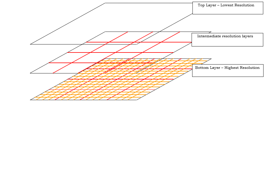
Figure 23 Terrain Pyramid
The Terrain SDK must be given enough information to determine the optimal level to use. Whenever the extent of the area of terrain data you are interested in changes, you must tell the Terrain SDK of the new extent. The Terrain SDK will then reconfigure itself for the new extent. If the area of interest changes but the extent remains the same (i.e. during a pan operation) then it is not necessary to notify the Terrain SDK.
Lining it All Up (Coordinate Systems)
When a map is prepared using MapLink Studio, the map is generated in a specific coordinate system defined by the MapLink Studio project. The same is also true for Terrain Databases generated using MapLink Studio. Therefore, when working with the Terrain SDK it is important to know what coordinate system the Terrain Database uses.
All functions within the Terrain SDK that take coordinates as a parameter expect the coordinates to be in Map Units (MU). Map Units are defined by the Output Coordinate System defined in the MapLink Studio project. They are generally in metres, but this does not always have to be the case. For example, if a terrain database is generated using the MapLink “Default Coordinate System” i.e. no coordinate system is configured; the Map Units will be in plain old WGS84 Latitude/Longitude positions. Whereas if the output coordinate system is configured as UTM Zone 30 North, the Map Units will be in metres with the origin being the centre of the projection.
The Terrain SDK provides functions to allow the coordinate system to be queried as well as allowing conversion between MU and latitude/longitude. If you want to check if the currently loaded terrain database is in a coordinate system that your application can handle, then add the following code after the call to open the terrain database.
Add this code after the call to terrainDB->open() to ensure the loaded terrain database is using the default coordinate system:
TSLCoordinateSystem* cs = terrainDB->queryCoordinateSystem();

// In most cases cs will not be NULL but older versions of the

// Terrain Database did not support coordinate system queries

// therefore we must check the return value of

// queryCoordinateSystem()

if ( cs )

{

// Make sure the coordinate system is the default coordinate

// system so we can assume the Map Units are in Latitude/Longitude

if ( stricmp( cs->name(), "Default Coordinate System" ) != 0 )
{

// Not the default coordinate system - display an error

}

}
The TSLCoordinateSystem object returned by TSLTerrainDatabase::queryCoordinateSystem can be used to convert from MU to Latitude/Longitude and vice versa. In addition, the same methods have been provided in the API interface to TSLTerrainDatabase. The TSLTerrainDatabase methods are functionally identical to the TSLCoordinateSystem methods and are provided purely for convenience.
The first method for transforming coordinates uses TSLCoordinateSystem:
TSLCoordinateSystem* cs = terrainDB->queryCoordinateSystem();

if ( cs )

{

double muOutX, muOutY;

double latOut, lonOut;

if ( cs->latLongToMU( latIn, lonIn, &muOutX, &muOutY ) )
{

// Conversion successful

}

if ( cs->MUToLatLong( muInX, muInY, &latOut, &lonOut ) )

{

// Conversion successful

}

}
The second method for transforming coordinates is more convenient:
double muOutX, muOutY;

double latOut, lonOut;

if ( terrainDB->latLongToMU( latIn, lonIn, &muOutX, &muOutY ) ==

TSLTerrain_OK )

{

// Conversion successful

}

if ( terrainDB->MUToLatLong( muInX, muInY, &latOut, &lonOut ) ==

TSLTerrain_OK )

{
// Conversion successful

}
How Do I Access the Data?
Once a terrain database has been opened, querying the data is simple. There are three methods provided which allow the database to be queried. The choice of query function you use is dependent on your application - choose the function that is most convenient. Each of the query functions returns whether the query was successful or not. Possible return values for the query functions are:
| TSLTerrain_OK | The query was successful. |
|---|---|
| TSLTerrain_NoData | There was no data in the database for the requested position. |
| TSLTerrain_??? | Any other error conditions |
To query a line of 10 points from the database:
TSLTerrainDataItem dataItem[10];

if ( terrainDB->queryLine( muXstart, muYstart, muXend, muYend,

10, dataItem ) == TSLTerrain_OK )

{

// Query successful. The information about the point is

// stored in the dataItem array

}
To query a single point from the database:
TSLTerrainDataItem dataItem;

if ( terrainDB->query( muX, muY, &dataItem ) == TSLTerrain_OK )

{

// Query successful. The information about the point is

// stored in dataItem

}
To query a 10 x 5 grid from the database:
TSLTerrainDataItem dataItem[10*5];

if ( terrainDB->queryArea( muBlX, muBlY, muTrX, muTrY,

10, 5, dataItem ) == TSLTerrain_OK )

{

// Query successful. The information about the point is

// stored in the dataItem array. The data is stored row-by-row

}
In each case, the data is returned in one or more TSLTerrainDataItem objects. For efficiency, by default the query functions will only populate the fields that define the requested position and the height/depth. It is important to note that even if the query function returns TSLTerrain_OK, the height value may not be valid. This is because some databases may contain ‘holes’ in their data coverage. This is indicated by the TSLTerrainDataItem::m_isNull flag being set - see the table below.
You may have noticed that one of the optional parameters to the query functions is a “filter”. This is used to define which fields to populate. The data returned by each filter is defined in the table below:
| Field | Filter | Description |
|---|---|---|
| m_x | TSLTerrainData_Min | MU X position of queried data |
| m_y | TSLTerrainData_Min | MU Y position of queried data |
| m_z | TSLTerrainData_Min | Height/Depth of requested position in metres |
| m_isNull | TSLTerrainData_Min | Flag that is set to true if no data existed at the requested position. If set to false, the m_z member contains valid data |
| m_nearestX | TSLTerrainData_Nearest | Contains the MU x position of the nearest actual point within the terrain database |
| m_nearestY | TSLTerrainData_Nearest | Contains the MU y position of the nearest actual point within the terrain database |
| m_nearestZ | TSLTerrainData_Nearest | Contains the height value for the point in the database at m_nearestX, m_nearestY. This field is only valid if m_nearestIsNull is false |
| m_nearestIsNull | TSLTerrainData_Nearest | If true, m_nearestZ is not valid otherwise it is valid |
| m_xResolution | TSLTerrainData_HorizontalRes | Defines the spacing of columns in the grid. The value is in MU. |
| m_yResolution | TSLTerrainData_HorizontalRes | Defines the spacing of rows in the grid. The value is in MU. |
Some of the fields in TSLTerrainDataItem are unused in the current implementation of the Terrain SDK. Only the fields in the table above are currently used.
Any number of filters can be combined to retrieve the required information. TSLTerrainData_Min is always added regardless of what other filter flags are set. A convenient definition is provided to get all available data: TSLTerrainData_All.
What Happens When There Is No Data for a Point? (Interpolation)
The simple answer is for the situation when a point is requested outside the extent returned by a call to TSLTerrainDatabase::queryExtent. In this case, the function just returns TSLTerrain_NoData. No further information is available. If, however, the point lies within the extent but between actual entries in the database rather than directly on an entry, a value is returned. The Terrain SDK calculates this value depending on the interpolation parameter passed into the query function.
Available values for the interpolation parameter are:
| TSLTerrainInterpolate_NONE | A nearest neighbour algorithm is used that returns the height of the point nearest the requested point. Very fast but less accurate. |
|---|---|
| TSLTerrainInterpolate_LINEAR | Bilinear interpolation is used to calculate height value. More accurate but slightly slower. |
| TSLTerrainInterpolate_MIN, TSLTerrainInterpolate_MAX | The lowest/highest neighbouring value is used. Very fast but rarely used due to their inaccuracy. |
Whichever interpolation value is used, the filter parameter can be used to determine the position and height value of the nearest point to the requested location. This can be useful when for reasons of accuracy; only actual values stored within the database are to be used in an application. This is illustrated in the code below:
To query a single point from the database getting all available associated information:
TSLTerrainDataItem dataItem;

if ( terrainDB->query( muX, muY, &dataItem, TSLTerrainData_All )

== TSLTerrain_OK )

{

// Query successful. All information about the point is

// stored in dataItem

}
How Accurate is My Data? (Querying Different Levels)
Referring back to section 17.3, we remember that the Terrain Database is stored in a pyramid structure to allow very quick queries of the data. How does the Terrain SDK know which pyramid level we want to use? In some cases, we want to obtain the most accurate height value for a location. How do we make sure we use the most detailed layer?
The second question in the paragraph above is the easiest to answer; “How do we make sure we use the most detailed layer?” There is one more optional parameter for the query functions that we haven’t looked at yet. Setting the Boolean parameter, highestRes to true notifies the Terrain SDK that we want the height value to be read from the highest resolution layer that contains the requested point. Setting it to false will allow the Terrain SDK to optimise the speed of the request at the expense of some of the accuracy.
Beware when using the highestRes parameter when covering a large area of the terrain database - the query could take a substantial amount of time.
To query a single point from the database using the highest resolution layer available. Note the “true” parameter to the query function that informs the Terrain SDK that we want the highest resolution data.
TSLTerrainDataItem dataItem;

if (terrainDB->query(muX, muY, &dataItem, TSLTerrainData_Min, true)

== TSLTerrain_OK )

{

// Query successful. Highest resolution data obtained

}
To query a single point from the database getting all available associated information:
TSLTerrainDataItem dataItem;

// Use bilinear interpolation for a more accurate result

if ( terrainDB->query( muX, muY, &dataItem,

TSLTerrainData_Min | TSLTerrainData_Nearest, false,

TSLTerrainInterpolate_LINEAR ) == TSLTerrain_OK )

{

// Query successful.

// m_x and m_y contain the requested location.

// m_z contains a value obtained by bilinear interpolation

// m_nearestX, m_nearestY and m_nearestZ contain the location

// and height/depth of the nearest stored data in the database

}
Onto the other question: “How does the Terrain SDK know which layer in the pyramid to use?” The simple answer is: you have to tell it! The mechanism for telling the Terrain SDK what resolution of data you want has been designed to tie-in with a MapLink application that displays map data. A quick explanation is required:
In most MapLink applications, a map display is provided and the user is given controls to pan, zoom, etc. Quite often, the Terrain SDK is incorporated into the application to allow the user to perform queries on terrain data. For example, the application can display a cross-section of the terrain between two points when the user drags a line over the map display. You can see from this example that it is pointless querying more points from the terrain database than can be displayed by the resolution of the screen. The Terrain SDK takes advantage of this and adjusts the pyramid level accordingly.
This is surprisingly simple to setup within a MapLink application - all you need to do is tell the Terrain SDK whenever the map extent changes - i.e. on a zoom operation or when the map window size changes. Note that it is not necessary to tell the Terrain SDK when the map is panned as this does not change the extent of the map.
In the handler for the MapLink map zoom command, notify the Terrain SDK of the new extent.
if ( m_drawingSurface->zoom( 25, true, false ) )

{

// Zoom was successful. Tell the Terrain SDK

// The function that notifies the Terrain SDK requires the size

// of the map window and the new extent. Assume the map window

// is the same size as this window

CRect rc;

GetClientRect( rc );

// Get the extent of the data. We need to convert this to MU. This

// assumes the MU of the map and of the Terrain SDK are the same

double muX1, muY1, muX2, muY2;

if ( m_drawingSurface->getMUExtent( &muX1, &muY1, &muX2, &muY2 ) )
{

// We have enough information now

terrainDB->displayExtent( rc.Width(), rc.Height(), muX1, muY1,

muX2, muY2 );

// That's it! Terrain database optimised for this

// screen resolution

}

InvalidateRect( 0, FALSE ) ;

}
Contouring
The Terrain SDK also allows for the generation of contour lines or polygons from the same height information used in a terrain database. The format that the generated contour information is displayed in is controlled entirely by the application via the use of rendering callbacks.
Providing Data for Contouring
The data to contour is expected in the form of a TSLTerrainContourVertexList of TSLTerrainContourVertex objects. Each vertex object represents data at a single point, and when all vertices are combined, they should form a regular or irregular grid inside the list object.
Each vertex can store one or more pieces of height information, named ‘attributes’, for the point it represents. Each of these attributes can be used to model different information about the point that the vertex represents. For example, the first attribute might be height information for the terrain at that point, a second attribute might be a recorded temperature value at that point and a third attribute might be a humidity value. Contour information can be generated separately for each of these attributes. Each vertex within the list must have the same number of attributes.
This example shows loading of height information from a terrain database and storing the data in a TSLTerrainContourVertexList ready for the generation of contour lines.
// Process the terrain data into a terrain database

if( m_terrainDB.open( terrainDBFile.c_str() ) != TSLTerrain_OK )

return false;

// Query the extent of the terrain data

long x1, y1, x2, y2;

if( m_terrainDB.queryExtent( x1, y1, x2, y2 ) != TSLTerrain_OK )

return false;

// Inform the terrain database of the size of our drawing surface

// so it can determine a good resolution for the data

long duMinX, duMaxX, duMinY, duMaxY;

m_drawingSurface->getDUExtent( &duMinX, &duMinY, &duMaxX, &duMaxY );

m_terrainDB.displayExtent( duMaxX - duMinX, duMaxY - duMinY,

x1, y1, x2, y2 );

// Read the data from the terrain database

TSLTerrainDataItem *dataItems =

new TSLTerrainDataItem[ m_terrainGridWidth * m_terrainGridHeight ];

if( m_terrainDB.queryArea( x1, y1, x2, y2, m_terrainGridWidth,

m_terrainGridHeight,

dataItems ) != TSLTerrain_OK )

{

return false;

}

// Convert the terrain database to contour vertices so we can give

// them to the contour object

TSLTerrainContourVertexList *vertices =

new TSLTerrainContourVertexList();

for( int i = 0; i < m_terrainGridHeight; ++i )

{

for( int j = 0; j < m_terrainGridWidth; j++ )

{

vertices->addVertex(dataItems[(i * m_terrainGridWidth ) + j].m_x,

dataItems[(i * m_terrainGridWidth ) + j].m_y,

1,

&dataItems[(i * m_terrainGridWidth) + j].m_z);

}

}

// Height information is now stored in the vertex list so the data

// from the terrain database is no longer required

delete[] dataItems;

TSLTerrainContour contour = new TSLTerrainContour();

// Give our vertex list to the contour object so we can then perform

// contouring - the contour object assumes ownership of the vertex

// list

contour->setVertices( vertices );
Although the contour object assumes ownership of the vertex list, the data contained within the list can still be modified by the application without having to generate a new vertex list and setting it on the contour object. This avoids having to do large copies when you wish to modify the data used for contouring. If this is done, the TSLTerrainContour object should be informed of the change via the notifyChanged() method in order to ensure that the updated data is used for future contouring operations.
Types of Contours
Contour information can be generated either as polygons or lines. When generating contours as lines there are three different algorithms that can be used, specified by the TSLTerrainContourLineType enumeration. The simplest of these is TSLTerrainContourLineTypeSimple which uses a Triangulated Irregular Network (TIN) to calculate the contour lines. TSLTerrainContourLineTypeStandard uses a similar method but performs some optimisation on the resulting contour lines to remove duplicate points from the calculated contours. TSLTerrainContourLineTypeCONREC uses a different algorithm that in most cases produces contour lines as good as those generated by the simple or standard methods but is substantially faster.
When generating contours as polygons there is no algorithm choice to make.
Drawing the Contours
Contours generated from the TSLTerrainContour class are passed to the application via one of the TSLTerrainContourCallbacks virtual methods. Which callback is invoked is dependent on which type of contour (see section 17.8.2) was requested according to the following table:
| Callback | Used by |
|---|---|
| TSLTerrainContourCallbacks::progress | All |
| TSLTerrainContourCallbacks::drawLine | TSLTerrainContour::drawContourLine using the following types: TSLTerrainContourLineTypeSimple TSLTerrainContourLineTypeCONREC |
| TSLTerrainContourCallbacks::drawPolygon | TSLTerrainContour::drawContourPolygon |
| TSLTerrainContourCallbacks::drawPolyline | TSLTerrainContour::drawContourLine using the following types: TSLTerrainContourLineTypeStandard |
| TSLTerrainContourCallbacks::drawText | TSLTerrainContour::drawContourLine using the following types: TSLTerrainContourLineTypeStandard |
| TSLTerrainContourCallbacks::drawTIN | TSLTerrainContour::drawTIN |
You should override each of the callbacks that will be used for your selected method of contour generation. The TSLTerrainContourCallbacks class provides default implementations of all the callbacks so that you only need to implement the ones that you are interested in.
The callbacks will be invoked numerous times before the original draw call returns. In order to prevent excessive redrawing your application should wait until the draw call has returned before updating the display of your application.
This example shows an implementation of the
TSLTerrainContourCallbacks::drawPolyline() callback in which the generated contour lines are added to a TSLStandardDataLayer to be drawn to the screen after contour generation has finished.

void TerrainContouringView::drawPolyline (TSLTerrainContourVertexList* vertices, double attribute)

{

// The coordinates of the vertices given to us are in the coordinate

// system of the terrain data, which may not be the same as that of

// the map we have loaded. Therefore it may be necessary to

// convert the coordinates so the contour lines appear in the correct

// place on the map.

TSLCoordinateSystem *terrainCS =

m_terrainDatabase->queryCoordinateSystem();

const TSLCoordinateSystem *mapCS =

m_mapDataLayer->queryCoordinateSystem();

bool needToConvert = false;

if( terrainCS->id() != mapCS->id() ||

terrainCS->getTMCperMU() != mapCS->getTMCperMU() )

needToConvert = true;

TSLCoordSet *coords = new TSLCoordSet();

// Process the list of vertices given to us into a polyline so we can

// display it on the map in a standard data layer

for( int i = 0; i < vertices->numberOfVertices(); ++i )

{

TSLTerrainContourVertex &vertex = vertices->at(i);

TSLTMC tmcX = 0, tmcY = 0;

if( !needToConvert )

{

// The terrain database and map coordinate systems are the same

terrainCS->MUToTMC( vertex.x(), vertex.y(), &tmcX, &tmcY );

}

else

{

// Convert between the terrain database and map coordinate systems

double lat = 0.0, lon = 0.0;

terrainCS->MUToLatLong( vertex.x(), vertex.y(), &lat, &lon );

mapCS->latLongToTMC( lat, lon, &tmcX, &tmcY );

}

coords->add( tmcX, tmcY );

}

TSLEntitySet *es = m_contourLayer->entitySet();

TSLPolyline *line = es->createPolyline( 0, coords, true );

if( line )

{

line->setRendering( TSLRenderingAttributeEdgeStyle, 1 ) ;

// Determine line colour based on the height of the contour

long colour = ( 255 / m_maxTerrainHeight ) * attribute;

line->setRendering( TSLRenderingAttributeEdgeColour,

TSLDrawingSurface::getIDOfNearestColour( colour, 0, 255 - colour) );

line->setRendering( TSLRenderingAttributeEdgeThickness, 1 ) ;

}

}
Drawing the Contour Labels
When drawing contour lines using TSLTerrainContourLineTypeStandard there is the option to draw labels for the generated contour lines. This is enabled by passing a non-NULL value to the textPrefix parameter of the TSLTerrainContour::drawContourLine() method, which will be passed to the TSLTerrainContourCallbacks::drawText() callback. This is usually set to a description of what the value in the label will represent (e.g. ‘Height:’ or ‘Temperature:’), but if nothing is desired can be set to an empty string.
When using text labels with the alignment value set to TSLVerticalAlignmentMiddle the contour lines are split at appropriate points around the labels so that the lines do not run through the labels themselves. As the contents of the labels are controlled via the application by the TSLTerrainContourCallbacks::drawText(), this necessitates informing the contour object of the maximum length that the text strings will be when the TSLTerrainContour::drawContourLine() method is invoked.
One way of doing this is to create a dummy text object of the longest expected length and use this to determine the size to pass in as follows:
TSLText *textObj = m_contourLayer->entitySet()->createText( 0, 0, 0,

maxLengthLabel.str().c_str(), 100 );

// It is necessary to set up the following attributes on the text object

// for updateEntityExtent() to work

textObj->setRendering( TSLRenderingAttributeTextSizeFactor,

m_textSizeFactor );

textObj->setRendering( TSLRenderingAttributeTextSizeFactorUnits,

TSLDimensionUnitsMapUnits );

textObj->setRendering( TSLRenderingAttributeTextFont, 2 );

// Set an entity ID on the temporary text object so we can remove it

// once we're done

textObj->entityID( INT_MAX );

m_contourLayer->notifyChanged();

// Store the currently viewed area of the map. In order to calculate the

// extent of the text object we need to change the viewed area so that

// our temporary text object would be visible

double viewedUUX1, viewedUUY1, viewedUUX2, viewedUUY2;

m_drawingSurface->getUUExtent( &viewedUUX1, &viewedUUY1,

&viewedUUX2, &viewedUUY2 );

double newUUX1, newUUY1, newUUX2, newUUY2;

long newSizeArea = 2 * m_textSizeFactor;

m_drawingSurface->MUToUU( -newSizeArea, -newSizeArea,

&newUUX1, &newUUY1 );

m_drawingSurface->MUToUU( newSizeArea, newSizeArea,

&newUUX2, &newUUY2 );

m_drawingSurface->resize( newUUX1, newUUY1,

newUUX2, newUUY2, false, true );

// Now calculate the size of our text object

m_drawingSurface->updateEntityExtent( textObj );

TSLEnvelope env = textObj->envelope( m_drawingSurface->id() );

unsigned long envWidth = env.width();

// Now we have the width of the text object in TMCs we need to convert this to the terrain database units

double lat1, lon1, lat2, lon2, x1, y1, x2, y2;

m_drawingSurface->TMCToLatLong( env.bottomLeft().x(),

env.bottomLeft().y(), &lat1, &lon1 );

m_drawingSurface->TMCToLatLong( env.topRight().x(),

env.topRight().y(), &lat2, &lon2 );

m_terrainDB.latLongToMU( lat1, lon1, &x1, &y1 );

m_terrainDB.latLongToMU( lat2, lon2, &x2, &y2 );

// This is the width of the text labels in the terrain database units

// with some additional space either side

width = ( x2 - x1 ) * 1.5;

// Now we have the width we no longer need our text object

m_contourLayer->removeEntity( INT_MAX );

// Finally, reset the viewied area of the map back to what it was originally

m_drawingSurface->resize( viewedUUX1, viewedUUY1,

viewedUUX2, viewedUUY2, false, false );
Performance Notes
Calculating contours can take a considerable amount of time when given large amounts of data to work on. As the result of a draw operation will not change if the data remains the same, it is more sensible to store the results of the contouring operation in a form that allows for fast rendering. The example in section 17.8.3 does this by creating geometry objects for each contouring line and storing them in a TSLStandardDataLayer. This prevents needless recalculation of the same points on each draw in the application.
Intervisibility/Viewshed Calculations
The Terrain SDK provides the ability to perform point-to-point line of sight calculations, along with area viewshed/intervisibility calculations. An area viewshed determines which points can/cannot be seen from a given start point by performing multiple line of sight calculations.
This functionality is exposed via a flexible set of classes, allowing the calculation to be integrated with a variety of applications. This API is currently only provided via the C++ interfaces.
The viewshed API consists of the following object types:
-
Input objects
-
Location filter objects
-
Algorithm objects
-
Compositor objects
-
Output objects
These objects must be combined in order to create a complete viewshed calculation pipeline. Basic implementations of these objects are provided so that a calculation can be performed with minimal effort.
Except for the algorithm object an application may provide custom implementations of these objects in order to provide application-specific input data and display results in an efficient manner.
Input objects
Input objects (TSLTerrainVSInput) define the interface used by the viewshed algorithms in order to retrieve source data. The input object exposes terrain data as a 2-dimensional array of doubles and a geographical extent.
The following implementations are provided:
-
TSLTerrainVSInputArray - This basic implementation can expose application-provided data to the viewshed algorithm.
-
TSLTerrainVSInputTerrainDatabase - This is a more advanced input object, which exposes a MapLink terrain database (TSLTerrainDatabase) to the viewshed algorithm. In a similar manner to the terrain data queries, this object will select an appropriate level of detail from the database for the desired output size/extent.
-
TSLTerrainVSInputEarthCurvature - This class wraps an existing input object and applies height corrections to compensate for earth curvature. Curvature corrections can be based on a visual or radar line of sight.
Location Filters
The location filter interface (TSLTerrainVSLocationFilter) is provided as a means of limiting the viewshed parameters to specific locations. The exact manner in which these filters are applied depends on the specific viewshed algorithm. Some algorithms may apply the filter to every input point, but some may not.
The API documentation for each viewshed algorithm specifies how these filters are applied to the process.
Algorithm Objects
Algorithm objects (TSLTerrainVSAlgorithm) contain the core viewshed functionality. They are responsible for performing calculations with the specified parameters and using the provided input/filter/compositor/output objects as needed.
The following viewshed algorithms have been provided:
-
TSLTerrainVSAlgorithmRFVS - An algorithm object, based on the RFVS [Frankil and Ray 1994] algorithm.
The following parameters may be used when calculating a viewshed:
-
Start/Centre point
-
Start height (Absolute or relative to ground)
-
End height (Absolute or relative to ground)
-
Maximum Radius
The resolution and extent of a viewshed output is a combination of the input object’s extent/resolution, and the specified parameters.
Compositor and Output Objects
Compositor objects (TSLTerrainVSCompositor) are provided with the results of the viewshed calculation. Each point in the calculation is passed to the compositor, along with:
-
Whether the point can be seen from the viewshed’s centre.
-
The height of the point, including any height offsets/corrections applied during the calculation.
The following compositor object implementations are provided:
-
TSLTerrainVSCompositorVisibility - A basic compositor which will store the visibility of each point in the output object.
-
TSLTerrainVSCompositorCumulative - A basic compositor which will store the visibility of each point in the output object. This compositor can be used to accumulate the output of multiple viewshed calculations, in order to determine which areas can/cannot be seen from a set of points.
Output objects (TSLTerrainVSOutput) are used for storing result data, by the provided compositor objects.
The following output object implementations are provided:
- TSLTerrainVSOutputArray - A basic output object which will store data in a 2-dimensional array.
The provided implementations are designed so that any compositor can be used with any output object. This allows an application to perform viewshed calculations with minimal effort, however the generic interface between the compositor and output objects results in reduced calculation performance.
Most applications should implement their own compositor object. This allows the viewshed results to be rendered immediately without first going through an output object.
Single Point-to-point Line of Sight
// Set up the input object, using the current display size, and extent

// The provided extent/display size will determine which level of detail

// is used within the terrain database.

TSLTerrainVSInputTerrainDatabase* input =

new TSLTerrainVSInputTerrainDatabase(&m_terrainDatabase,

displayExtent, displayWidth, displayHeight);

// Setup the viewshed algorithm

// For single LOS calculations, the RFVS algorithm doesn't require

// a compositor object.

// It does however require an input object, to calculate whether

// the line is blocked by terrain.

TSLTerrainVSAlgorithmRFVS algorithm(input, NULL);

// Determine whether the end point can be seen from the start point.

// If it cannot, the 'blocked' point will be populated

double LOSStartX = -122.0;

double LOSStartY = 37.0;

double LOSStartZ = 100.0;

double LOSEndX = -121.5;

double LOSEndY = 37.35;

double LOSEndZ = 0.0; // Sea level

// Storage for the 'blocked' point

double LOSBlockedX = 0.0;

double LOSBlockedY = 0.0;

double LOSBlockedZ = 0.0;

if( algorithm.calculateLineOfSight(

LOSStartX, LOSStartY, LOSStartZ,

LOSEndX, LOSEndY, LOSEndZ,

LOSBlockedX, LOSBlockedY, LOSBlockedZ)

== TSLTerrainVSAlgorithmRFVS::LOSResultBlocked )

{

// The end point is not visible from the start point.

// The point where the line is blocked is stored in

// LOSBlockedX, LOSBlockedY, LOSBlockedZ

}

// The end point is visible from the start point.

// Release our references

input->dec();
Area Viewshed Using Provided Classes
The following example performs a single viewshed calculation using application-provided terrain data.
Note: As this example uses the generic compositor/output objects it is not the fastest method of performing a viewshed, nor the recommended approach for most applications. This approach should mainly be used when performance is not critical and the results do not need to be displayed immediately.
// Create an input object array, at the specified size/extent.

// Data should be populated from the application-specific source.

// 100 x 100 sample grid, covering -30.0,-60.0 to 30.0,60.0.

// The provided coordinate system is EPSG:4326 (A valid coordinate system must // be provided for viewshed calculations)

TSLTerrainVSInputArray* input = new TSLTerrainVSInputArray(

100, 100,

TSLMUExtent(-30.0, -60.0, 30.0, 60.0),

coordSys4326);

// Create an output object to store viewshed results.

// This object should be created with the same extent/size as the input object.

// The output may be re-used for multiple viewsheds, however this basic

// implementation only provides basic validation of the coordinates.

TSLTerrainVSOutput::dataItem defaultVal;

defaultVal.type = TSLTerrainVSOutput::typeTSLTerrainVSVisibility;

defaultVal.data.v = TSLTerrainVSVisibility::TSLTerrainVSNoData;

TSLTerrainVSOutputArray* output = new TSLTerrainVSOutputArray(

input->width(), input->height(),

input->queryExtent(), defaultVal);

// Create a compositor object.

TSLTerrainVSCompositorVisibility* compositor =

new TSLTerrainVSCompositorVisibility(output);

// Create the algorithm object.

TSLTerrainVSAlgorithmRFVS algorithm(input, compositor);

// Perform a viewshed calculation.

// The format of the data, and interpretation of results is defined by the

// compositor object.

// In this case, the visibility of each point will be stored in the output

// array.

algorithm.calculateViewshed(

centerX, centerY,

startHeightOffset, startRelativeToGround,

maximumRadius, endHeightOffset, endRelativeToGround);

// Release our references

input->dec();

compositor->dec();

output->dec();
Performance Considerations
The overall performance of the viewshed algorithm mainly depends on the efficiency of the input/compositor objects, the extent of the viewshed calculation, and the resolution of the terrain data.
The RFVS viewshed algorithm, as used in the terrain viewer, is generally fast enough to be considered ‘real-time’ when performing calculations up to 10,000 x 10,000 samples (Running on an Intel dual-core processor @ 3.6GHz). For example, if the source terrain data has a post-distance of 20m the performance should be acceptable with a maximum radius of up to 100km. If the terrain data is of a higher resolution, or the maximum radius parameter is increased, then the performance will be decreased accordingly.
If using the TSLTerrainVSInputTerrainDatabase class an appropriate level of detail will be selected from the terrain database. However, the lowest detail in the database may still be too high if attempting to perform a very large viewshed. Where possible the post distance of the data should be checked and the viewshed radius limited accordingly.
The RFVS viewshed algorithm will use multiple threads where available so any application-defined objects must be threadsafe. The maximum number of threads used by the algorithm may be specified via the TSLTerrainVSAlgorithm::maxThreads method.
Application Integration
This section details how to integrate the viewshed functionality with an application. This is intended for applications which need to overlay viewshed results on a map display.
An example of this is provided by the ‘Terrain Viewer (C++ and MFC)’ sample application.
This application allows the following viewshed parameters to be adjusted:
Start/centre point
Start height (Absolute or relative to ground)
End height (Absolute or relative to ground)
- Maximum Radius
Correction for earth curvature (Visual or radar)
Result visualisation colours
Input Object Setup
If using a MapLink terrain database, the application simply needs to create an instance of TSLTerrainVSInputTerrainDatabase.
TSLTerrainVSInputTerrainDatabase::displayParameters should be called before performing each viewshed, to ensure that the correct extent/data resolution is exposed via the input object. In the terrain viewer, this happens as part of TSLViewModeArea::performViewshed and CTerrainViewerDoc::calculateViewshed.
The input object will query data from the nearest level of detail. This means that the viewshed calculation will be performed at the data resolution, and the results will need to be resized by the compositor when drawn to the screen.
The application may use other sources of data through the provided TSLTerrainVSInputArray class or by providing an application-specific input object.
The terrain viewer also creates an instance of TSLTerrainVSInputEarthCurvature. This is used as the input object if earth curvature corrections have been enabled in the options. Enabling earth curvature correction will decrease the viewshed performance as it adds an additional calculation to each sample point.
Application-Specific Compositor
In order to display the viewshed results the terrain viewer defines the CTerrainClientCustomDataLayer class. This class inherits from both TSLTerrainVSCompositor, and TSLClientCustomDataLayer.
When a viewshed calculation is performed the results are passed to CTerrainClientCustomDataLayer::setData. This method stores the viewshed results directly into a Windows HBITMAP. This is then drawn over the map via the TSLClientCustomDataLayer::drawLayer method.
This approach enables the application to perform calculations without making unnecessary copies of the data and with a minimum number of function calls. It also allows the rendering of the results to be controlled as a MapLink data layer.
The compositor in the terrain viewer has been designed for single-threaded use only. If an application is going to perform viewsheds over a large area they should be performed in a background thread in order to keep the application responsive.