Threading
This section applies to the Core SDK, Terrain SDK, 3D SDK, Accelerator SDK and Dynamic Data Object SDK only. With other SDKs ensure that you do not share objects across threads.
Introducing multi-threading complicates matters as MapLink is not completely thread safe. This is principally to ensure maximum performance.
You should review the whole of this section if you are going to use MapLink in multiple threads.
If you are using MapLink for drawing in multiple threads, then you may need to use the following methods:
-
TSLUtilityFunctions::getThreadedOptions
-
TSLUtilityFunctions::setThreadedOptions
The following classes have been updated to provide additional functions which do not store results in static data:
-
TSLCoordinateConverter
-
TSLProfileHelper
-
TSLPathList
-
TSLCoordinateConverter
-
TSLFileLoader
-
TSLInteropConfig
-
TSLInteropExportSet
-
TSLInteropImportSet
The following methods are no longer static:
-
TSLMapDataLayer::setRuntimeProjectionParameters (C++ /.NET)
-
TSLAPPSymbol::write
Known Threading Issues
The following are known not to be thread-safe and you should stop all threads before performing any of the following (PLEASE read the following sections as well):
-
Any method noted as Deprecated by the compiler should be updated to use the new replacement method.
-
Loading and adding CoordinateSystems and CoordinateSystem registries.
-
Static setter methods are not thread safe. For example, you should make sure that if you set your own loader or pathlist on the Drawing Surface that this occurs before your application starts any threads using MapLink (or stop all threads using MapLink outside of MapLink methods).
-
Don’t share Display connections between threads on X11. Resources are keyed on the Display.
-
Seamless Layer Manager is not thread safe.
-
Flashback is not thread safe.
-
History is not thread safe.
-
DBIF is not thread safe.
-
Entity Store SDK is not thread safe.
-
S63 SDK is not thread safe when saving data.
-
Don’t setup a Persistent cache with shared layers.
-
Sharing Drawing surfaces between threads is not safe.
-
TSLErrorStack interface is not thread safe, use the TSLThreadedErrorStack.
The following Core SDK methods and classes are also known not to be thread safe. If you need to call the methods from a multi-threaded context protect the calls and copy the results immediately.
-
TSLCompareHelper
-
TSLVariant::id (use getID)
-
TSLMapDataLayer::getPaletteFilename
-
TSLMapDataLayer::getPathlistFilename
-
TSLMapDataLayer::getDetailLayerName
-
TSLMapDataLayer::getOverviewLayer
-
TSLMapDataLayer::metadata
-
TSLErrorStack::first (use TSLThreadedErrorStack)
-
TSLErrorStack::index (use TSLThreadedErrorStack)
-
TSLErrorStack::lastError (use TSLThreadedErrorStack)
-
TSLErrorStack::next (use TSLThreadedErrorStack)
-
TSLErrorStack::previous (use TSLThreadedErrorStack)
-
TSLProfileHelper
-
TSLInteropConfig::basefilename
-
TSLInteropConfig::groupingAttribute
-
TSLInteropExportSet::item
-
TSLInteropImportSet::item
-
TSLMapDataLayer::copyRasterFeatures
-
TSLSeamlessLayerManager::setMapLinkVersion
-
TSLUtilityFunctions::sav( int arg )
-
TSLPathList::getMatchingDirectories
(use getMatchingDirectoriesMT)
Threading Options
Several threading options can be set or cleared when using MapLink. Currently the only one that you should consider using is the TSLThreadedOptionsRenderingSupport (also see 28.6).
The threading options may be set and queried using the following methods:
-
TSLUtilityFunctions::setThreadedOptions
-
TSLUtilityFunctions::getThreadedOptions
Saving Data
MapLink allows you to save data as the current version or as a previous version.
The setting of the version is not local to a layer but is stored globally, because of this we currently take a global lock to ensure data is written out in the correct version.
Drawing Surface ID
The drawing surface ID that the user can set is no longer used by MapLink. We now create a unique value internally.
The user ids must be positive values. If the user does not set one the internal unique id is returned as a negative number.
Drawing Surface Resource Loading
In general, you should setup the Drawing Surface resources before your application goes multi-threaded. The line-styles, fill-styles, fonts and symbols are a shared resource and take time to load. The loading is thread-safe however the propagation of the new resources is lazy and only occurs on a draw.
Note: Delayed loading of resources is not thread-safe.
Drawing Surface Rendering
While in general the drawing is thread safe you should avoid sharing layers between threads (see 28.8).
If you wish to share the TSLStandardDataLayer (see 28.9) between threads then you need to call TSLUtilityFunctions::setThreadedOptions to set the bit represented by TSLThreadedOptionsRenderingSupport.
Coordinate System Resource Loading
The loading of the Coordinate System information (TSLCoordianteSystem::loadCoordinateSystems) is not thread safe and therefore the coordinate systems should be loaded before the application uses MapLink in a threaded manner. A map loads and creates a coordinate system local to the layer so it is not strictly necessary to load all the Coordinate Systems unless you need to convert between different projections.
Data Layers
The following types of data layers must not be shared between threads:
-
Map Data Layers
-
CADRG Data Layers
-
Raster Data Layers
-
WMS Data Layers
-
Filter Data Layers
-
All Grid Data Layers
-
ECW Layer
-
Dynamic Object Data-layer and the Display Objects
Adding or removing a layer from a drawing surface is not thread safe. Stop all drawing surfaces that the layer is to be added to or removed from before adding or removing.
Standard Data Layer
Sharing the standard 2D data-layer is safe as long as the Drawing Surface IDs are different for each thread (see 28.6).
You must not edit (add or remove entities) the layer unless you stop the drawing in all threads the layer has been added too.
The changing of rendering styles is permitted, though the updating of the drawing maybe delayed.
Custom Data Layer
It is the responsibility of the developer to ensure that the layer is thread-safe.
If you are adding a Custom 2D Data Layer to an Accelerator or 3D surface, you should note that the layer will be called from a back-ground thread.
Dynamic Rendering
It is the responsibility of the developer to ensure that the dynamic renderer is thread-safe.
If you are adding a dynamic renderer to an Accelerator or 3D surface then you should note that the layer will be called from a back-ground thread
TSLPathList
TSLPathList is not thread safe unless the application takes the following measures:
-
Do not use the callback.
-
If you are setting up a pathlist for the Drawing Surfaces to use; Set up the drawing surface pathlist object and add this to the drawing surface before your application starts using multiple threads.
-
If you need to change the drawing surface pathlist or modify it after your application has started its threads; Stop all threads outside of MapLink calls and do the necessary modifications.
-
If you are setting up a pathlist for data layers; Ideally use a separate pathlist per map data-layer (do not share cached layers between drawing surfaces in different threads). If you need to share the pathlist between map data-layers then only modify the pathlist when all threads using MapLink are stopped outside of MapLink method calls.
User Geometry
It is the developer’s responsibility to ensure thread safety for the user implemented functionality
Dynamic Data Object Layer
The Dynamic Data Object Layer should not be shared between Drawing Surfaces in different threads.
The layer and its associated objects should only be modified from the thread containing the associated Drawing Surface.
Terrain SDK and Contouring SDK
Terrain can be used in multiple Threads as long as the terrain layer (TSLTerrainDatabase) is unique for each thread (not shared between threads).
The Contouring SDK has not been used in a threaded manner and thus may not be thread-safe. The Contouring SDK modifies the floating-point registry to enable strict IEEE floating point and as such is unlikely to be thread-safe.
3D SDK & Accelerator SDK
Both the 3D and Accelerator Drawing surfaces use a background thread for drawing 2D layers.
The 3D SDK and the Accelerator SDK clone their Map, CADRG and WMS Data Layers to ensure thread safety. These layers can be shared between Drawing Surfaces in the same thread.
Other data-layers are not currently cloned and as such you should not share these layers between multiple drawing surfaces, with the exception of the 2D Standard Data Layer (see 28.9). In addition, you should stop the drawing surfaces before modifying the layers in any-way.
All data layer types, except the S63 and ECW Data-layer, should be acceptable to the 3D SDK and Accelerator SDK. If you need to use these layers with the 3D or Accelerator SDK please contact support.
-
Drawing should always occur from the thread that created the Surface.
-
Sharing Drawing surfaces between threads is not safe.
-
Picking with 3D Surface is not thread safe. Picking must occur in the main drawing thread.
-
Removing and deleting 3D entities is not thread safe. Removing and deleting of entities must occur in the main drawing thread.
-
Deleting a layer in a thread other than the main drawing thread is not thread safe (deletion of OpenGL/DirectX resources will occur).
Accelerator Drawing Surface Rendering
While in general the drawing is thread safe you should avoid sharing layers between threads (see 28.8).
If you update a layer’s content the changes will not be reflected upon the display until you have called notifyChanged on the surface.
3D Drawing Surface Rendering
While in general the drawing is thread safe you should avoid sharing layers between threads (see 28.8).
If you wish to share the TSL3DStandardDataLayer between threads, you must call TSLUtilityFunctions::setThreadedOptions to set the bit represented by TSLThreadedOptionsRenderingSupport. In addition, you must add the layer to all drawing surfaces before you start any drawing and you should not edit the layer once drawing has occurred.
Ideally you should not share the TSL3DStandardDataLayer between threads principally because we store data upon the entities which is drawing surface specific and the locking will affect the performance of the drawing.
X11 Threading
On X11 you must either serialise the calls to MapLink or use a separate display connection for each drawing surface.
Resources are allocated on a display basis and are cached in MapLink based on the Display as the key.
Use of separate display connections in each thread is the safe way to use MapLink. Sharing of Display connections may appear to work until you start using processors with multiple cores or a multi-processor system.
You should call XInitThreads() before any other Xlib calls in your application as the Xlib library and generally the extensions are not thread safe until this method has been called. You may need to review the source code of the libraries you use as we know that the Xft extension is not thread safe.
We have found that XInitThreads() is not always required if you limit your use to Xlib and avoid Xft (or protected access to Xft methods - see 28.2 and 12.6.9), however this is a case of test and review the client side library source code as the versions you are using may be very different from the ones we have used. Additionally, we have ensured that we do not share X resources between drawing surfaces.
The principle drawing limitation in a threaded environment is the X-Server. The X-Server is a single process so all drawing calls will be serialised at the X-Server. This is not necessarily a problem as MapLink and your application may be able to do something else in the dead time.
Synchronisation calls are kept to a minimum within the X11 Drawing Surface.
Developers Guide UNIX/Linux/VxWorks (X11)
MapLink has been ported to a variety of operating systems (OS), the common denominator being that X11 is available for those operating systems.
Limitations which are specific to a particular OS and compiler configuration can be found in the X11 Release Notes.
The principles outlined in the ‘Developers Guide for MapLink’ are applicable for use with MapLink on an X11 platform. This section covers the differences between Windows and X11 runtime programming.
Programming for X11
TSLMotifSurface
The primary programming difference between Windows and X11 is the Drawing Surface class that you use. For X11 you will use: TSLMotifSurface (should really have been called X11DrawingSurface).
There are two constructors for this class:
-
TSLMotifSurface (Display* display, Screen* screen, Colormap colormap, Drawable handle, int flags = 0, Visual* visual = 0);
-
TSLMotifSurface (Display* display, Drawable handle, int flags = 0);
Ideally you should pass as much information to MapLink as possible. This is particularly important when using raster maps, as the actual Visual is required so that the correct raster drawing routines can be used.
TSLMotifSurface is a simple class, which provides several additional X11 specific methods, which also have similar methods on the TSLNTSurface as follows:
-
int colourValue (int index);
-
bool fillStyleValue (int index, int colour, Pixmap pixmap, TSLSimpleString *section = 0);
-
bool fontStyleValue (int index, int colour, Pixmap pixmap, const char** fontName = 0, const char *outputString = 0, TSLSimpleString *section = 0);
-
bool lineStyleValue (int index, int colour, int thickness, Pixmap pixmap, TSLSimpleString *section = 0);
-
bool symbolStyleValue (int index, int colour, Pixmap pixmap, uint32_t fontSymbolCharacter = 0, TSLRasterSymbolScalable rasterSymbolScalability = TSLRasterSymbolScalableAsSymbolFile, TSLSimpleString *section = 0);
-
bool drawToDrawable (Drawable drawable, double x1, double y1, double x2, double y2, bool clear);
-
bool attach (Drawable handle, bool isPixmap, Display* display = 0, Screen* screen = 0, Colormap colormap = -1, Visual* visual = 0);
-
bool fullDetach ();
All the above methods are specific to X11 (not all the default parameters are shown).
When creating an application for X11, regardless of GUI toolkit, the principles behind the ‘Walkthrough 1 - Your First MapLink Application’ are just as valid. Some samples are included with the CD to help you.
Actions on close of Display
You should call TSLDrawingSurface::cleanup() before you close the Display.
Using GUI Toolkits with MapLink
MapLink does not depend on any particular GUI toolkit to work. MapLink relies only on Xlib.
It is therefore possible to use MapLink with any number of GUI toolkits, such as Motif or Qt (https://www.qt.io/).
We now ship samples for Qt 4.7 and Qt 5.15.
Using Qt4.X
If you have difficulty integrating MapLink with Qt please contact support.
Add a method to the Custom Widget as follows:
virtual QPaintEngine *paintEngine() const

{

return 0;

}
This stops Qt drawing into the Widget itself.
In the Custom Widget constructor add the following:
// This is required for Qt4 to stop the back ground being drawn

// and Qt Double buffering. You also need to override

// paintEngine().

//

// Ref:

// <http://lists.trolltech.com/qt-interest/2006-02/thread00004-0.html>

//

setAttribute( Qt::WA_NoBackground, true);

setAttribute( Qt::WA_NoSystemBackground, true);

// Possible issue with this for Qt4.1.0 and newer versions.

//

// See:

// <http://www.trolltech.com/developer/task-tracker/index_html?id=106922&method=entry>

// <http://lists.trolltech.com/qt-interest/2006-05/thread00316-0.html>

//

// Talk to Trolltech support about getting a fix if this proves to

// be a problem

//

// NOTE: I am not seeing this problem, probably because I'm doing

// things slightly differently from the example.

setAttribute( Qt::WA_PaintOnScreen, true);

setAutoFillBackground(false); //should be true for Qt4.1 and 4.0
For Qt4.1 and newer you will need to add the following:
setAttribute(Qt::WA_OpaquePaintEvent);
When you construct the MapLink Drawing Surface use the winId or handle method as follows:
// Attaching to the window is much more efficent.
#ifdef WINNT
HWND hWnd = (HWND) winId();

m_drawingSurface = new TSLNTSurface( hWnd, false );
#else

QX11Info x11info = this->x11Info();

Display *display = x11info.display();

int screenNum = x11info.screen();

Visual *visual = (Visual *)x11info.visual();

Qt::HANDLE colourmap = x11info.colormap();

Qt::HANDLE drawable = handle();

Screen *screen = ScreenOfDisplay(display, screenNum);

m_drawingSurface = new TSLMotifSurface( display, screen, colourmap,

drawable, 0, visual);

#endif
The paintEvent in the Custom Widget should look something like this:
void MapLinkWidget::paintEvent ( QPaintEvent *rect )

{

if (m_drawingSurface == NULL)

create();

if (m_initialUpdate)

resizeCanvas();

const QRect &r = rect->rect();

long x1 = r.x() ;

long y2 = r.y() ;

long x2 = r.x() + r.width() ;

long y1 = r.y() + r.height() ;

m_drawingSurface->drawDU( x1, y1, x2, y2, true, true ) ;

}
Using Qt 5.1 or later
Add a method to the Custom Widget as follows:
virtual QPaintEngine *paintEngine() const

{

return NULL;

}
This stops Qt drawing into the Widget itself.
In the Custom Widget constructor add the following:
setAttribute( Qt::WA_OpaquePaintEvent );

setAttribute( Qt::WA_PaintOnScreen );

setAttribute( Qt::WA_NativeWindow );

setAutoFillBackground( false );
When you construct the MapLink Drawing Surface use the winId method as follows:
#ifdef WIN32

m_surface = new TSLNTSurface( (HWND)winId(), false );

#elif QT_VERSION >= 0x50100

// Qt 5.1 or newer

Display *display = QX11Info::display();

WId wid = winId();

XWindowAttributes attribs;

XGetWindowAttributes( display, wid, &attribs );

m_surface = new TSLMotifSurface( display, attribs.screen, attribs.colormap, wid, 0,

attribs.visual );

#else

// Qt 5.0 does not provide easy an easy way of accessing the X11 display or drawable

// for the widget. It is recommended that you upgrade to Qt 5.1 or later.

#endif
Drawing on top of MapLink using Qt
In order to use Qt to draw on top of MapLink rendering, you will need to draw the map data into a QtPixmap and blit the QtPixmap to the screen. The code to disable the Qt double buffering and background clearing is probably no-longer required depending on what you are trying to achieve.
Text Drawing
The X11 drawing code now uses Pango to draw text so that we can support Unicode. On most platforms Pango uses Xft and hence XRender.
On ‘Solaris 10 x86’ we have had to use the latest Xft because the one shipped is too old to work effectively with XRender. The version of Pango we are using is the latest one that we were able to compile using the development environment available on the platform.
On ‘Solaris 10 SPARC’ the version of Pango we are using is the latest one that we were able to compile using the development environment available on the platform.
Dynamic Data Object SDK
Dynamic Data Object (DDO) SDK allows developers to create fully dynamic overlays within a MapLink application (see Developers Guide).
When you create a TSLDisplayObject derived class you have two options when implementing the draw method.
-
Make a sequence of calls to the Rendering Interface to set up attributes and draw graphical primitives (portable).
-
Draw using X11 drawing methods (non-portable, optimal).
Obtaining the Display and Drawable can be achieved as follows:
bool AircraftDO::draw(TSLRenderingInterface *d_surface,

TSLEnvelope *d_extent )

{

long ldisplay;

Drawable drawable = (Drawable)

(d_surface->handleToDrawable( &ldisplay ));

Display* display = (Display*)ldisplay;

// ......

}
The TSLRenderingInterface also provides access to the Visual, Colormap and Screen. This will make it easier to create pixmaps and images in a custom data layer or via a DDO.
Raster support
All MapLink X11 targets support the display of Raster Maps locally or remotely. The X-Server depth to use (via the Visual) will be dependent on the X-Server and the applications use of colour.
The X11 MapLink runtime supports TIFF, PNG and JPEG formats generated by MapLink Studio (not all combinations of these formats are supported).
Raster datasets from MapLink Studio may be configured to output at a particular bit-depth and for 8-bit images, the number of colours used by the image may be specified. Note: that the default is 24-bit (Please refer to the MapLink Studio help).
Rasters which contain an alpha channel will only be displayed correctly when using X servers that support XRender 0.6 or later.
Holed Polygons
Vector Maps can be generated from MapLink Studio with holed polygons or without holes by using key-holing.
Using key-holing means that the drawing of holed polygons is a lot less complex and more efficient. Therefore, this is the recommended approach on X11 for performance reasons alone.
The only reason for not using this approach is if a polygon edge line style is required to be displayed as this will show the keyhole construction.
Note: VxWorks target Envitia uses for testing does not support drawing of holed polygons.
APP-6A and 2525B Symbology
MapLink provides the capability to display many APP6A and 2525B symbols through two classes (TSLAPP6AHelper & TSLAPP6ASymbol).
MapLink provides two configuration files, app6aConfig.csv and 2525bConfig.csv in the config directory of your MapLink installation. Applications should pass the full path to one of these files depending on which set of symbology is desired.
In addition to these configurations the alternate symbol file ‘tslsymbolsAPP6A.dat’ has been provided. This also includes OTHT-Gold symbols. Any application using APP-6A or 2525B icons should load this symbols file. It is acceptable simply to load it using ‘setupSymbols’ after calling ‘loadStandardConfig’. See the Windows APP-6A sample.
Stroked Linestyles
Stroked linestyles are implemented by an extension shared library (ttlclsstrk.so/sl/o). The shared library is written specifically for the target platform.
The file tsllinestyle.dat contains many stroked linestyle definitions, an example of a stroked linestyle is shown below:
1000;ttlclsstrk;My Custom Line;MyCustomLineStyleTag;C[(-1,-1,-1),4]U[0,-2]D[5,0]D[5,0]BC[(-1,-1,-1),2]U[0,1]D[5,0]D[5,0]D[4,0]
The above line is broken down as follows:
StyleID;typeOrCustomDLLName;Textual comment displayed in feature book, no semi-colons allowed;DLL specific information
For the ttlclsstrk.so/sl/dll (DLL) which implements this type of line, the DLL specific information is:
UniqueTag;CommandString
The CommandString is a chain of
C[(R,G,B),W] colour and width, RGB obvious, W width (width <= 0 is set to 1 pixel). If R, G and B are all -1, then colour defined by feature book is used.
D[x,y] Pen down, line to (currentPositionX + x, currentPositionY + y)
U[x,y] Pen up, move to (currentPositionX + x, currentPositionY + y)
B Bend Point. This is where we can effectively start a new line segment.
Where:
Pen Down means place the drawing point on the paper and draw to the specified position from the current position.
Pen Up means raise the drawing point off the paper and move to the specified position from the current position.
All moves are relative to the current position.
The easiest approach when creating or modifying a Stroked Linestyle is to use a pen and a piece of graph paper, recording exactly how you draw the line (pen up, pen down, colour, amount moved).
So for ‘D[5,0]U[5,0]D[5,0]’, you get the following simple line:
’----- -----‘
Where:
- represents pen colour being drawn (Pen Down) as a solid line, but here represented as dashes to show the amount of movement of the Pen.
space represents pen colour not being drawn (Pen Up)
The start point of your line is always at position [0, 0].
In the above simple line at the end of the sequence the current drawing position is [0, 15].
So if you wanted to return to [0, 0], you would add ‘U[0,-15]’ to the line definition.
Please note the following:
-
When drawing a custom linestyle Maplink uses the horizontal axis where y=0, as the middle of the line.
-
Progress has to be made in the x-axis.
-
The line thickness is specified in pixels. So a line thickness of three will be drawn in a similar way that Windows/X11 will draw a solid line of thickness 3.
-
Line segments are drawn with a round end cap on Windows. On X11 line segments are drawn with CapButt and JoinMiter.
-
You can also increase the number of ‘B’s to improve the ability of the customline style to follow the draw points.
In general ‘B’ points must occur when the y-axis is at 0. If you make changes to a linestyle check the changes using a relatively complex map or drawing. -
Custom linestyles will have an impact on drawing performance. The more complex a linestyle the larger the impact on performance.
X11 Error Handlers
If you define Error handlers by calling XSetErrorHandler, then you need to call any error handlers already defined (XSetErrorHandler returns the previous error handler).
The Raster drawing shared library uses this error handler to detect problems when using shared memory (XShm). The MapLink3D optional SDK also hooks into the X error handling to figure out if it can use the XShm extension.
You should setup the X error handlers before you call MapLink or MapLink will call the default handlers if it does not handle the errors it-self. MapLink will not call any error handlers if it handles the errors itself.
It is possible to disable the setting up of the Error handlers by setting of the environment variable TTL_GDK_SHM_OFF.
Vector and Raster Data Format Support
The list of data formats supported by MapLink Pro Studio or runtime SDKs is constantly being expanded. The following sections describe some of the formats currently supported at the time of writing.
Vector Datasets
| Data Format | Studio Import | Direct Import SDK | Other Runtime Import | Runtime Export |
|---|---|---|---|---|
| DAFIF | ✔ | |||
| DFAD | ✔ | |||
| DXF | ✔ | ✔ | ||
| Envitia ASCII | ✔ | |||
| File Geodatabase (FileGDB) | ✔ | ✔ | ||
| GDF3 | ✔ | |||
| GeoPackage | ✔ | ✔ | ||
| GML2/GML3 | ✔ | ✔ | ✔ | ✔ |
| Jeppesen | ✔ | |||
| KML Simple Features 2D | ✔ | ✔ | ✔ | |
| MIF/MID | ✔ | ✔ | ✔ | ✔ |
| NITF/NSIF | ✔ | ✔ | ✔ | |
| OpenStreetMap | ✔ | ✔ | ||
| OS MasterMap | ✔ | ✔ | ✔ | ✔ |
| OS NTF | ✔ | ✔ | ✔ | ✔ |
| OS VectorMap Local | ✔ | ✔ | ✔ | |
| OS VectorMap District | ✔ | ✔ | ✔ | |
| OS Boundary Line 2000 | ✔ | ✔ | ||
| S-57 (Unencrypted ENC & AML) | ✔ | ✔ | ✔ | ✔ |
| S-57 Encrypted (S-63) | ✔ | |||
| ShapeFiles | ✔ | ✔ | ✔ | ✔ |
| US Census TIGER/Line | ✔ | ✔ | ||
| VPF (DNC, VMAP, WVS etc.) | ✔ | |||
| Other Vector (e.g. TAB, Spatialite/SQLite) | ✔ | ✔ |
Raster Datasets
| Data Format | Studio Import | Direct Import SDK | Other Runtime Import | Runtime Export |
|---|---|---|---|---|
| ADRG | ✔ | ✔ | ||
| ARCS Chart (Unencrypted) | ✔ | |||
| ASRP | ✔ | ✔ | ✔ | |
| BSB Nautical Chart Format | ✔ | ✔ | ||
| CADRG/CIB | ✔ | ✔ | ✔ | ✔ |
| CRP | ✔ | |||
| ECRG | ✔ | ✔ | ||
| ECW | ✔ | |||
| GeoPackage | ✔ | ✔ | ||
| Geospatial PDF | ✔ | ✔ | ||
| GeoTIFF | ✔ | ✔ | ✔ | |
| JPEG | ✔ | ✔ | ||
| JPEG2000 | ✔ | ✔ | ||
| MrSID | ✔ | ✔ | ||
| NITF/NSIF | ✔ | ✔ | ✔ | |
| USRP | ✔ | ✔ | ||
| Other Raster (e.g. IMG, PNG etc.) | ✔ | ✔ |
Deprecated SDKs
3D SDK
Envitia provide an integration to osgEarth, including display of symbology and draping of all MapLink Pro layers.
Please contact support@envitia.com or your sales representative for additional information.
The 3D SDK incorporates the advantages of 3D terrain data with existing MapLink maps to create a fully immersive environment for reviewing and exploring. Built to extend and strengthen the MapLink family of tools, the 3D SDK offers all of the advantages of the other components, but in a 3D environment.
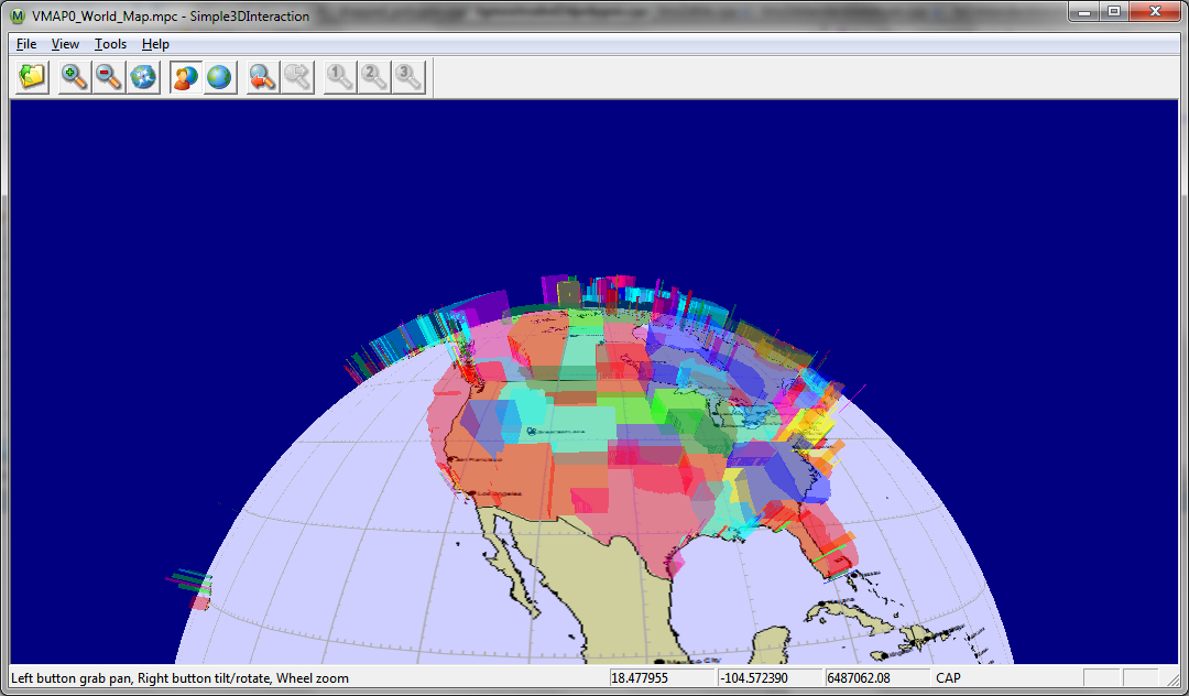
Figure 24 3D Globe with US States Extruded as polygons.
Library Usage and Configuration
| MapLink3D64.lib Release mode, DLL version. Uses Multithreaded DLL C++ run-time library. Requires TTLDLL preprocessor directive. Your application must also link the MapLink CoreSDK library MapLink64.lib and the OpenGL library opengl32.lib. Refer to the document “MapLink Pro X.Y: Deployment of End User Applications” for a list of run-time dependencies when redistributing, where X.Y is the version of MapLink you are deploying. |
Migrating from 2D to 3D
The MapLink 3D SDK is designed to be completely compatible with the 2D Core SDK and this makes migration very easy. It holds true to many of the Core SDK concepts such as the Document/View model of data being loaded on to a data layer, which are in turn loaded onto a drawing surface.
Another core MapLink concept that is continued in the 3D SDK is the passivity of the library. This greatly increases the flexibility of MapLink but like for the core SDK means that relevant events must be managed by the application and passed onto the 3D drawing surface.
Introduced with this SDK are a number of new data layers, each deriving from the base 3D data layer, TSL3DDataLayer. An example of such a layer is the TSL3DStandardDataLayer for 3D geometric entities which is the 3D equivalent to the TSLStandardDataLayer for 2D geometry. These new data layers, along with any necessary 2D data layers, should be attached to a derivative of the 3D drawing surface base class TSL3DDrawingSurface, such as TSL3DWinGLSurface for Windows.
The 3D Coordinate Space
All positions in the MapLink 3D world are specified in geodetic coordinates; latitude, longitude and altitude above the surface of the earth. It is possible to perform geodetic to geocentric conversions and the reverse using the TSL3DDrawingSurface where the geocentric coordinates x, y, z are from the centre of the earth and their unit is metres. Geodetic coordinates are also wrapped around the earth if they are specified outside of the coordinate space, such as passing over the poles or international data line.
Altitude can also be specified in a number of different ways using the TSL3DAltitudeType enum. It can be equated from the mean sea level or from the height above ground level at that point. The height above ground level can also be altered using a range of options to deduce the exact height to use at that point from the terrain data.
It is important to note that as bounding boxes of entities and entity sets are specified in geodetic coordinates, it is difficult to manipulate these with reference to the object they were calculated from. The TSL3DHelper class provides several helper functions to manipulate a TSL3DBoundingBox object, such as the ability to rotate, scale and translate them.
Threading
The 3D Drawing Surface uses a background thread for rendering of the 2D layers.
As such you should review the contents of section 28, in particular sections 28.8, 28.12 and 28.16.
Walkthrough 5 - Your First 3D Application
If you are familiar with the walkthroughs for the Core SDK then this tutorial might seem basic and could be run through quickly concentrating on the information that appears inside the boxes.
Skeleton Application
Please note that the Wizards are not available for Visual Studio 2015, see section Error! Reference source not found..
The starting point for this is an MFC Application Wizard generated executable. It can be either an SDI or MDI application, although MDI is not recommended. The example code here will be based upon an SDI application.
Configure Project Properties
Once created, build your skeleton application to ensure it compiles and links. You then need to set up the Project Properties according to the version of the MapLink libraries you wish to use with the corresponding 3D SDK library. These are described in sections 5.1 and C.1.1.
In the x64 Debug configuration make the following checks and modifications to the Project Properties:
In ‘C/C++’, ‘Code Generation’ category, check that the run-time library is “Multi-Threaded Debug DLL”
In ‘C/C++’, ‘General’ category, add the MapLink include directory as an additional include path, e.g.
“C:\Program Files\Envitia\MapLink Pro\X.Y\include”
In the ‘Linker’, ‘Input’ category, add MapLink64d.lib and MapLink3D64d.lib as object/library modules and in the ‘Linker’, ‘General’ category add the MapLink lib64 directory as an additional library path, e.g.
“C:\Program Files\Envitia\MapLink Pro\X.Y\lib64”
Make the same changes to the x64 Release configuration, except link against MapLink64.lib and MapLink3D64.lib instead.
Add #include “MapLink.h” and #include “MapLink3D.h” to relevant files. In this example, just add it into stdafx.h to keep things simple.
Note: X.Y is the version of MapLink you are using.
Initialisation and Clean Up
The configuration files for MapLink are usually only loaded once per execution run using static methods of TSLDrawingSurface. In an MFC application, these are normally loaded during the InitInstance method of the Application object. The simplest way is to tell MapLink to load all standard configuration files from a particular directory. If no directory is specified, then MapLink will assume that a full MapLink installation has taken place and will attempt to load from there.
In the InitInstance method of the App object, add a call to TSLDrawingSurface::loadStandardConfig. This should be done before the Document Template is instantiated.
You should be careful to check for, and report errors at this stage by using the methods supplied on the TSLThreadedErrorStack utility class.
const char * configDirPath = NULL ; // Replace if deployed

// Full path and filename to the file tsltransforms.dat

const char * transformsFile = NULL; // Replace if deployed

TSLThreadedErrorStack::clear() ;

TSLDrawingSurface::loadStandardConfig( configDirPath ) ;

// Required for draped polygons.

TSLCoordinateSystem::loadCoordinateSystems( transformsFile );

TSLSimpleString msg( "" );

bool anyErrors = TSLThreadedErrorStack::errorString( msg,

"Initialisation Errors : \n" ) ;

if ( anyErrors )

{

AfxMessageBox( msg, MB_OK ) ;

exit( 0 ) ;

}
When your application is deployed, make configDirPath variable point to the location of your applications copy of the MapLink config directory. The transformsFile will need to be handled in a similar manner.
Once MapLink has been initialised, it needs to be cleaned up when the application exits, otherwise Visual Studio will report numerous “leaks” which are in fact memory currently in use when the application exits. This should be done in the ExitInstance method of the App class. You will need to use the class Properties Overrides to add this method since the MFC Application Wizard doesn’t add it by default. Alternatively, in Single Document applications, it may be called in the destructor of the View or Document class.
Use Properties, Overrides to create an ExitInstance method on the App object. In this method, call MapLink to cleanup the configuration file load.
int CHelloGlobe::ExitInstance()

{

TSLDrawingSurface::cleanup( ) ;

return CWinApp::ExitInstance();

}
If you are using the DLL versions of the MapLink libraries, please note the discussion of memory leaks in section Error! Reference source not found..
Managing the Document
In terms of the Document/View architecture, the Document contains one or more MapLink Data Layers. This is where using the 3D SDK differs greatly from the 2D, for it offers a number of new Data Layers. For the purposes of this example application however, we shall restrict this to a single TSLMapDataLayer.
In the private section of the Document, declare a bool and a pointer to a TSLMapDataLayer object. The bool should be constructed to false, and the object should be constructed in the document constructor and then destroyed in the destructor:
CHelloGlobeDoc::CHelloGlobeDoc () : m_newMap( false )

{

m_mapDataLayer = new TSLMapDataLayer() ;

}
CHelloGlobeDoc::~CHelloGlobeDoc ()

{

if ( m_mapDataLayer )

{

m_mapDataLayer->destroy() ;

m_mapDataLayer = NULL ;

}

}
Use Properties, Overrides to create an OnOpenDocument handler and in this method, set you bool flag to true and store the filename in a member variable. Create a private method loadMap that takes no parameters and returns void
BOOL MapLink3DSimpleDoc::OnOpenDocument(LPCTSTR lpszPathName)

{

if (!CDocument::OnOpenDocument(lpszPathName)) return FALSE;

m_newMap = true ;

m_mapName = lpszPathName ;

return TRUE;

}
void MapLink3DSimpleDoc::loadMap()

{

if (!m_newMap) return ;

m_mapDataLayer->removeData() ;

TSLThreadedErrorStack::clear() ;

// Load map and then display any errors that have occurred

m_mapDataLayer->loadData( m_mapName.c_str() ) ;

TSLSimpleString msg( "" );

bool anyErrors = TSLThreadedErrorStack::errorString( msg,

"Cannot load map\n" ) ;

if ( msg )

AfxMessageBox( msg, MB_ICONERROR ) ;

else

m_mapDataLayer->notifyChanged() ;

}
Managing the View
In terms of the Document/View architecture, the View contains an instance of a TSL3DDrawingSurface derived object - TSL3DWinGLSurface on Windows platforms, TSL3DX11GLSurface on X11 platforms. This is the only significant platform-specific difference. In an MFC application, this is usually instantiated in the OnInitialUpdate method since the associated window doesn’t exist in the OnCreate event or in the View constructor.
In the private section of the View, declare a pointer to a TSL3DWinGLSurface object. This should be initialised to NULL in the View constructor.
Use Properties, Overrides to create an OnInitialUpdate handler and in this method, check to see if a Drawing Surface exists and create one if necessary. You can optionally also set a sky, wire frame and solid colours as well as drape a picture over the earth, as is done below. You will need a private member variable of type CString, called m_backdrop to allow you to do this. You should also tell MapLink about the default size of the window.
void CHelloGlobeView::OnInitialUpdate()

{

CView::OnInitialUpdate();

if ( !m_drawingSurface )

{

CRect rect ;

GetClientRect( &rect ) ;

// Create the drawing surface

m_drawingSurface = new TSL3DWinGLSurface ( m_hWnd, false );

// Give the 'sky' a colour!

static const TSLStyleID skyColourIndex( 4 );

m_drawingSurface->setBackgroundColour( skyColourIndex );

static int const wireframeColourIndex( 181 );

static int const solidColourIndex( 60 );

m_backdrop = TSLUtilityFunctions::getMapLinkHome();

m_backdrop += "/config/earth.png";

// Set the bitmap to display over the terrain plus colours

// for solid-backdrop and wireframe rendering.

m_drawingSurface->setTerrainRendering( wireframeColourIndex,

solidColourIndex, m_backdrop );

// Notify surface what size the window is

m_drawingSurface->wndResize(0, 0, rect.Width(), rect.Height());

// The following line is discussed in 12.5.9

m_drawingSurface->setRenderingCallback(renderingCallback, this);

}

}
In the destructor of the View, destroy the Drawing Surface if it exists.
CHelloGlobeView::~CHelloGlobeView()

{

if ( m_drawingSurface )

{

m_drawingSurface->destroy() ;

m_drawingSurface = NULL ;

}

}
Binding Layers and Drawing Surfaces
Once both Document and View are ready available, you need to attach the Data Layers to the Drawing Surface so that MapLink can display it.
The recommended approach to this is to create an addToSurface method on the Document, which calls the underlying MapLink routines to add the Document’s Data Layers to the Views Drawing Surface. This structure avoids the View knowing the contents of Document in any detail and is equally applicable to both Single and Multiple Document Interfaces.
The addToSurface method should be called in the OnInitialUpdate method of the View, just after the Drawing Surface has been created. In MFC applications, it is not usually necessary to have an equivalent deleteFromSurface method since MFC calls DeleteContents instead. If you are adding more than one Data Layer to the Drawing Surface, each must have a unique name.
Create a public addToSurface method in the Document that takes a TSLDrawingSurface pointer as a parameter. In this, add the Document’s Data Layer to the specified Drawing Surface.
bool CHelloGlobeDoc::addToSurface(TSL3DWinGLSurface *drawingSurface)

{

if ( !m_mapDataLayer || !drawingSurface )

return false ;

loadMap(); // load the map.

return drawingSurface->addDataLayer( m_mapDataLayer, "map" ) ;

}
Call this method in the View’s OnInitialUpdate method, after the Drawing Surface has been created. At this point, it is also appropriate to define the initial visible area. Here we call the reset method of the TSL3DCamera, before providing a position for the camera and the direction in which it is pointing. The workings of TSL3DCamera are discussed in 12.8.
if ( GetDocument()->addToSurface( m_drawingSurface ) )

{

m_drawingSurface->camera()->reset();

m_drawingSurface->camera()->moveTo( 50.0, 0.0, 10000000.0,

TSL3DCameraMoveActionNone ) ;

m_drawingSurface->camera()->lookAt( 50.0, -5.0, 0.0, false ) ;

}
Note that MapLink automatically takes care of Data Layer and Drawing Surface separation when either is destroyed.
Handling Resize Events
Since MapLink is passive, the application needs to handle relevant events and pass the information onto MapLink. Most applications will only need to handle the window resize and expose or paint events.
After handling a resize event, Windows or X will usually post a paint message so there is no need to force a redraw in the resize handler.
Use Properties, Messages to create a WM_SIZE handler on the View class since it is not there by default. In this method, check to see if a Drawing Surface exists and if so, pass the new corners of the window to the Drawing Surface using the wndResize method. This example will also inhibit an automatic redraw and ask MapLink to maintain the aspect ratio locking the top left corner of the visible map area.
void CHelloGlobeView::OnSize(UINT nType, int cx, int cy)

{

CView::OnSize(nType, cx, cy);

if ( m_drawingSurface )

{

m_drawingSurface->wndResize( 0, 0, cx, cy, false );

}

}
Handling resize events differs from the 2D to the 3D as we are not given the option of providing a flag to indicate an anchor point that the resizing takes place around. This is because the TSL3DCamera takes care of this control and is discussed in section 12.8.
Handling Paint Events
In the OnDraw method of the View, query the required redraw area and pass it to the Drawing Surface, asking MapLink to clear the background first.
void CHelloGlobeView::OnDraw(CDC* pDC)

{

if ( m_drawingSurface )

{

RECT rect ;

if ( pDC->GetClipBox( &rect ) == NULLREGION )

GetClientRect( &rect ) ;

m_drawingSurface->drawDU( rect.left, rect.bottom,

rect.right, rect.top, true ) ;

}

}
A paint event can be triggered for many reasons, some of which will only want to redraw part of the window. Under these circumstances, Windows will set up a Clip Box to define the part that needs redrawing. To improve performance it is best to only redraw that part. It is most efficient to pass the required Device Unit extent to the Drawing Surface.
To create a 3D application you must also provide a TSL3DRenderingCallback triggered when draped data is ready to be rendered. This is a static method that returns a void and takes a void*.
Create a new static method in the View with the following implementation:
void Simple3DInteractionView::renderingCallback(void * arg,

int pendingTextures )

{

Simple3DInteractionView * view = (Simple3DInteractionView *)arg ;

if ( view->m_hWnd )

{

view->Invalidate() ;

}

}
Now build the program, run it and load one of the sample maps.
Reducing Flicker and Improving Performance
So far, the application is not making use of MapLink performance optimisations and the display will appear to flicker when it is redrawn. There are two reasons for this. Firstly, MapLink is drawing directly to the window. Secondly, both MapLink and Windows are clearing the display prior to the redraw. In depth discussion of these problems and their solutions may be found in section 12.5. In the meantime, here are a couple of quick fixes to reduce your eyestrain! Please be aware this will only work for SDI applications and not for MDI applications.
To solve the first issue, a single method call should be added when the Drawing Surface is created to make it buffered. This will also improve performance on expose events that are not due to the visible map area changing.
To solve the second issue, you should inhibit Windows from clearing the window.
Use Properties, Messages to add a View handler for the WM_ERASEBKGND message. Return TRUE from this method to indicate to windows that the application will erase the background.
BOOL CHelloGlobeView::OnEraseBkgnd(CDC* pDC)

{

return TRUE ;

}
The inhibition of the WM_ERASEBKGND message is appropriate since MapLink is drawing to the entire window. If MapLink were drawing to only part of the window then it may be necessary for the application to erase the areas that MapLink is not rendering into.
3D Standard Data Layers
The TSL3DStandardDataLayer class is a Data Layer, just like the other derivatives of TSLDataLayer that have been discussed in this developer guide such as the 2D equivalent TSLStandardDataLayer. As such, it may be created and added to one or more Drawing Surfaces from whence the contents are displayed. It is a specialist data layer for the handling of non-map 3D data, providing the ability to load, create, manipulate and save non-map 3D data as well as a number of miscellaneous functions.
In the same way that a TSLStandardDataLayer contains instances of TSLEntity derived objects and the TSLObjectDataLayer contains instances of TSLDynamicDataObject derived objects, the TSL3DStandardDataLayer contains instances of TSL3DEntity derived objects.
3D Entities
A further 2D Core SDK concept that has been continued in the 3D SDK is the use of geometry Entities. All geometric objects in MapLink can be thought of as Entities, derivatives of TSLEntity in the 2D and of TSL3DEntity in the 3D.
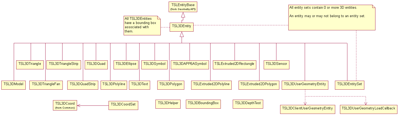
Figure 25 3D Entity Hierarchy
In the 3D SDK all entities with the exception of user geometry have a number of properties including:
-
A bounding box defined in 3D space
-
A set of rendering attributes that specify how the entity appears.
-
One or more TSL3DCoord objects that define the position and in most cases the orientation and size of the entity.
TSL3DEntity
This is the base class for all 3D geometric primitives and gives access to the methods and properties common to all its derivatives. These include the ability to query the type of derivative an entity is, the bounding box, the centre of the object and the distance this entity is from a specific point. Other operations perform movement and scaling functions and equality comparisons.
TSL3DModel
This class defines a common interface to 3D models that can be loaded via plug-ins. The model to draw is determined by setting the TSLRenderingAttributeModelStyle rendering attribute to an index from tslmodels.dat.
Multiple Levels of Detail can be set for a model to allow for progressively lower polygon-count models to be used when the model is further away from the camera.
TSL3DTriangle and TSL3DQuad
Both of these shapes are basically restricted types of polygon; they are limited to having 3 or 4 point and may not have inners. They can be created like the other multipoint 3D entities by passing a TSL3DCoordSet or uniquely they can be created by passing the individual TSL3DCoord objects. Also like other multipoint geometric shapes, their area and perimeter can be queried. A quad specifically must be non-complex, meaning there are no intersecting edges, and all points must lie in a plane.
The order of point specification is anti-clockwise.
TSL3DTriangleFan and TSL3DTriangleStrip
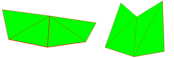
These 3D geometric objects provide a quick way of creating multiple adjoining triangles that use the same rendering attributes. Both are created from closed, filled, 3 point triangles and behave similarly.
For a TSL3DTriangleFan, the first point defines the common centre point of the fan. The first three points of the fan define a 3D triangle. Each subsequent point defines a triangle made up of the common centre point, the previous point and the new point. For a TSL3DTriangleStrip, the first three points of the strip also define a 3D triangle. Each subsequent point defines a triangle made up of the new point and the previous two points
TSL3DQuadStrip
This is the 4 point version of TSL3DTriangleStrip and is formed in much the same way; each pair of added points forms a quad with the previous pair. Each contained 3D quad must be non-complex. All points of each contained 3D quad must lie in a plane.
TSL3DPolyline
This is the 3D version of TSLPolyline which always has length and may or may not have area depending upon whether the polyline is closed. If a polyline is closed then the first and last points are joined by a vertex, except if they exist at the same 3D position in which case the polyline is already closed. A closed polyline can therefore be thought of as being a polygon; the length property becomes the equivalent to its perimeter and it now has the concept of area.
A polyline must have at least two points, although a closed polyline should logically have at least three, but other than that there are no limitations placed upon the coordinates.
TSL3DPolygon
A TSL3DPolygon is a closed, filled, planar feature with three or more constituent points. It always has a perimeter length property and an area, but due to it being planar it can never have volume. It must be non-complex, meaning its edges must not cross, although they may touch.
A 3D polygon may also have one or more holes also known as inners, with the main polygon also being known as the outer. These inners are basically cut out sections of the polygon which may not touch or cross the outer, nor touch or cross any other hole. The outer nor inners may have consecutive duplicate points.
Draped Polygons, including extruded, have a number of limitations. The applicable limitations are listed in the Release Notes.
For draped polygons to work TSLCoordinateSystem::loadCoordinateSystems() must be called before the 3D SDK is used.
Extruded 2D Primitives
These extruded shapes, TSLExtuded2DPolygon, TSLExtruded2DPolyline and TSLExtruded2DRectangle consist of a MapLink 2D shape that has been given an extrusion and placed at a set altitude in a 3D world. They are created around the 3D shape, which can be queried or changed for another without destroying the extruded shape. These shapes have identical properties to their 2D counterparts, most of which are accessible by first querying this object for its 2D object.
TSL3DEntitySet
This is a collection of other 3D Entities, but is also an entity itself so can contain other Entity Sets and thus be hierarchical. It has no geometric attributes of its own, but inherits its bounding box as the union of its children’s. Like the 2D version of this object, the TSL3DEntitySet differs from the OpenGIS specification of an entity collection by allowing different types of entity to be contained.
3D User Geometry
This is the 3D version of user geometry.
A 3D user geometry entity allows the user to create custom-drawn geometry upon 3D standard data layers. User geometry can be saved to and loaded from TMF files. A piece of 3D user geometry is composed of two parts, the entity (an instance of TSL3DUserGeometryEntity, managed by MapLink) and the client (an instance derived from TSL3DClientUserGeometryEntity, managed by the user).
TSL3DUserGeometryEntity
This is the 3D version of TSLUserGeometryEntity.
Instances of TSL3DUserGeometryEntity can be added to 3D standard data layers, and are allocated and deallocated by MapLink. Create instances by calling TSL3DUserGeometryEntity::create, or by calling create3DUserGeometry on a TSL3DEntitySet. The client of a 3D user geometry entity can be set and retrieved by calling setClientUserGeometryEntity and getClientUserGeometryEntity, respectively.
create, create3DUserGeometry, setClientUserGeometryEntity and load callback functions all provide a takeOwnership flag. If true, then MapLink will automatically delete the client if it is replaced with setClientUserGeometryEntity or when the entity is destroyed. If false, the user will have to destroy the client. This must be false if the user’s code is compiled with a different compiler or runtime library version to MapLink.
Creating and destroying user geometry:
TSL3DStandardDataLayer* stdLayer = ...;

TSL3DClientUserGeometryEntity* client = new ...;

TSL3DUserGeometryEntity* entity = stdLayer->entitySet()->

create3DUserGeometry(client, false);

if (!entity)

... // handle error

...

entity->destroy();

delete client; // don't need this if takesOwnership is true
TSL3DClientUserGeometryEntity
This is the 3D version of TSLClientUserGeometryEntity.
The user creates clients by deriving from TSL3DClientUserGeometryEntity, and creating their own instances of these subclasses. A client can then be attached to an entity as explained above.
At a minimum, the user must override the abstract draw and centre methods. It is however strongly recommended that boundingSphereRadius is also implemented within the client. In conjunction with the position returned from centre, the return value from boundingSphereRadius is used to perform view frustum culling of user geometry. The user should therefore ensure that the calculated bounding sphere radius is accurate for the entity being rendered in order to avoid user entities that are visible from being incorrectly culled.
Unlike 2D geometry, view frustum culling is performed on TSL3DEntitySets as well as individual entities. If the size of the user geometry changes it is necessary to manually update the bounding boxes of its parent TSL3DEntitySet as the previous bounding box may no longer be correct. This is done by calling updateBoundingBox on the TSL3DEntitySet that contains the TSLUserGeometryEntity object associated with the client. This entity set can easily be retrieved by using the parent method of the TSLUserGeometryEntity.
Within the draw function, the entity will be positioned such that (0,0,0) in model space is at the location returned by the user’s centre method with the positive Z-axis perpendicular to the surface of the earth (ignoring terrain) at that point. This means that within a draw each user geometry object operates within its own local coordinate system, the units of which are metres. The exception to this is any drawing performed through methods on the TSL3DRenderingInterface that accept positions using TSL3DCoords, TSL3DCoordSets or a TSL3DEntity. Objects rendered in this fashion are drawn in the same positions as they would be if drawn from outside user geometry.
The OpenGL state on entry to draw is dependent on the entities that have been drawn so far in the current frame, and therefore will differ depending on the view of the application. The user should therefore make no assumptions about the OpenGL state on entry to draw other than the following:
-
The GL_COLOR_ARRAY, GL_EDGE_FLAG_ARRAY, GL_FOG_COORD_ARRAY, GL_INDEX_ARRAY and GL_SECONDARY_COLOR_ARRAY client states will never be enabled.
-
The matrix mode for the built-in matrix stack will be GL_MODELVIEW_MATRIX.
-
The active texture unit will be GL_TEXTURE0, however texturing may be either enabled or disabled.
-
There will be no active program bound.
MapLink internally tracks the OpenGL state in order to avoid redundant state changes. Therefore care should be taken to reverse any modifications made to the OpenGL state in before returning from draw as failure to do so may result in incorrect rendering of subsequent entities. This also applies to any rendering performed through the TSL3DRenderingInterface. Aside from this restriction the user is free to use any OpenGL functionality within draw in order to render the entity.
Here is an example partial implementation of a user geometry client:
class SquareClient : public TSL3DClientUserGeometryEntity
{
private:
TSL3DCoord m_centre;
double m_radius;
public:
// Constructor
SquareClient(TSL3DCoord centre)
: m_centre(centre)
, m_radius(sqrt(2000000.0*2000000.0 + 2000000.0*2000000.0))
{
}
// Destructor
virtual ~SquareClient()
{
}
virtual double boundingSphereRadius () const
{
return m_radius;
}
virtual const TSL3DCoord& centre () const
{
return m_centre;
}
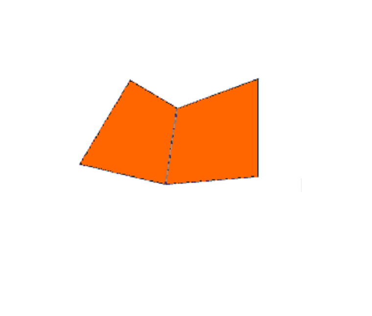
// render an orange square
virtual bool draw (int uniqueSurfaceID,
TSL3DRenderingInterface* renderingInterface)
{
glPushAttrib( GL_ALL_ATTRIB_BITS );
glPushClientAttrib( GL_CLIENT_ALL_ATTRIB_BITS );
GLfloat coords[] = { -100000.0f, -100000.0f, 0.0f,
100000.0f, -100000.0f, 0.0f,
-100000.0f, 100000.0f, 0.0f,
100000.0f, 100000.0f, 0.0f };
glColor4f( 1.0f, 0.5f, 0.0f, 1.0f );
glDisable( GL_TEXTURE_2D );
glDisable( GL_CULL_FACE );
glEnableClientState( GL_VERTEX_ARRAY );
glDisableClientState( GL_TEXTURE_COORD_ARRAY );
glDisableClientState( GL_INDEX_ARRAY );
glVertexPointer( 3, GL_FLOAT, 3 * sizeof( GLfloat ), coords );
glDrawArrays( GL_TRIANGLE_STRIP, 0, 4 );
glPopAttrib();
glPopClientAttrib();
return true;
}
// stream out the polygon
virtual int save (TSLofstream& stream)
{
...
return SQUARE_USER_GEOMETRY_ID;
}
};
Loading and saving 3D user geometry
The process is almost identical to that of 2D user geometry.
If the user wants their 3D user geometry classes to be saved and loaded along with other types of geometry, they need to override the save method on the client, and to provide a load callback function to the static method TSL3DUserGeometryEntity::registerUserGeometryClientLoadCallback.
The save method on the client should return a positive integer to identify the type of 3D user geometry. These numbers should be unique as they can be passed to any registered load callback function. It is suggested that the user publish and track these identifiers.
It is also suggested that the user saves, along with any geometry data, a company identifier, a byte-order mark, a geometry type ID and a version number.
To register a load callback function, a pointer to it must be passed to TSL3DUserGeometryEntity::registerUserGeometryClientLoadCallback. The pointer should have type TSL3DUserGeometryLoadCallback (which is a function pointer typedef). The pointer will be added to a list; when user geometry is loaded, each function on the list will be called until one returns non-NULL.
Setting a load callback function:
TSL3DUserGeometryEntity::

registerUserGeometryClientLoadCallback(loadUserGeometryCallback);
Here is a skeleton load callback function:
static TSL3DClientUserGeometryEntity* loadUserGeometryCallback(

TSLifstream& stream,

int userGeometryID,

bool& assumeOwnership)

{

// whether returned entities will be freed by MapLink:

assumeOwnership = ...;

switch (userGeometryID)

{

case SQUARE_USER_GEOMETRY_ID:

... // stream in client and return it

... // etc

default:

return NULL;

}

}
3D Custom Data Layers
It is possible to introduce your own custom drawn data to the MapLink 3D drawing surface using the TSL3DCustomDataLayer class. To accomplish this you must add an instance of this class to your drawing surface and attach to it your own derivative of the abstract class TSL3DClientCustomDataLayer.
Your derivative of the TSL3DClientCustomDataLayer class will need to override the pure virtual draw methods, which provide an interface class through which a number of useful functions such as querying if a point or bounding box falls within the viewing volume and coordinate conversion functions can be performed.
Using the Camera
The TSL3DCamera class provides the ability to manipulate the users’ view of the drawing surface. It has three main properties: its position, orientation and normal. The orientation is also known as its lookAt position whereas the normal is perpendicular to this and defines the direction from the centre to the top of the view.
The camera also provides the ability to specify its angle of view, also known as its field of view. This is by default 45 degrees. The camera also allows the user to set the altitude at which the horizon will appear horizontal in the field of view. This altitude should be set to a value at which the horizon has a meaningful definition (e.g. 1000 metres).
Integration with Other OpenGL Applications
It is sometimes desirable to use MapLink in conjunction with user interface toolkits or other libraries that perform their own OpenGL context creation. Depending on the constructor used, the MapLink 3D drawing surfaces can either create their own OpenGL context or use an existing context created externally. When using a drawing surface in this fashion, MapLink can be instructed not to perform buffer swaps through the swapBuffersManually constructor argument, leaving the application in control of when this occurs.
More information can be found in the API documentation for each platform’s drawing surface (TSLWinGLSurface for Windows, TSL3DX11GLSurface for X11 systems).
Creating a 3D Model Plug-in
MapLink provides an example plug-in named ttl3DS which is capable of loading files produced by 3D Studio Max. The source code to this plug-in can be found in the Samples directory of your MapLink installation.
Model plug-ins are loaded at runtime as models that use them are drawn, and are unloaded when those models are deleted. The plug-in that is used to load and draw a particular model is defined by the tslmodels.dat file that is passed to TSL3DDrawingSurface::setupModels(). A part of the entry for each model is a plug-in specific string which allows for custom options to be defined for each model and plug-in. New models should be added to this file and given the next available unique index. The count of the number of entries in the file should also be updated. A complete description of the format of this file can be found in the tslmodels.dat file provided in the config directory of your MapLink installation.
The Structure of a Plug-in
All plug-ins must be compiled as DLL/shared objects, and must declare a class that inherits from TSL3DCustomModel. An instance of this class will be created for each unique model defined in tslmodels.dat that uses this plug-in. In addition to this the DLL/shared object must export the following “C” methods:
extern "C" __declspec(dllexport)

void* getModel( int index,

const char* filename,

const char* pluginString );

extern "C" __declspec(dllexport) void deleteModel( void* model );
When a model is required the getModel() method will be invoked with the index from tslmodels.dat of the model, the full path to the model file and the plug-in specific configuration string. This method will only be invoked once for each model, and should return an instance of your derived TSL3DCustomModel class that is responsible for drawing this model.
When a model is no longer required the deleteModel() method will be invoked, with the object returned from the relevant getModel() call passed in as the parameter for cleanup by the plug-in.
Drawing a Model
A plug-in cannot make any assumptions about the state of the rendering engine when drawing, and should always reset any state changes it makes back to what they were originally before the draw() method returns.
Storing and resetting rendering state information in OpenGL.
bool N3DSModel::draw(int drawingSurfaceId, double distanceToEye,

int lodToDraw)

{

glPushAttrib( GL_ALL_ATTRIB_BITS );

// Change any required states and draw the model

glPopAttrib();

return true;

}
The model itself should be drawn around 0,0,0 and will be translated to the correct position by the 3D SDK. Since the draw() method will be invoked frequently for models that are visible in the application the plug-in should make use of optimisation techniques such as display lists to ensure that the drawing takes as little time as possible.
Any textures associated with a model can be loaded via the TSL3DTextureLoader utility class. The loadTexture() method available on this class returns the texture in a format suitable for passing to the appropriate texture functions used by the type of plug-in, for example glTexSubImage2D() for OpenGL. If the requested texture size differs from the actual size of the texture it will be resized to satisfy the request. For more information see the API class documentation.
Contouring
The Terrain SDK also allows for the generation of contour lines or polygons from the same height information used in a terrain database. The format that the generated contour information is displayed in is controlled entirely by the application via the use of rendering callbacks.
Providing Data for Contouring
The data to contour is expected in the form of a TSLTerrainContourVertexList of TSLTerrainContourVertex objects. Each vertex object represents data at a single point, and when all vertices are combined, they should form a regular or irregular grid inside the list object.
Each vertex can store one or more pieces of height information, named ‘attributes’, for the point it represents. Each of these attributes can be used to model different information about the point that the vertex represents. For example, the first attribute might be height information for the terrain at that point, a second attribute might be a recorded temperature value at that point and a third attribute might be a humidity value. Contour information can be generated separately for each of these attributes. Each vertex within the list must have the same number of attributes.
This example shows loading of height information from a terrain database and storing the data in a TSLTerrainContourVertexList ready for the generation of contour lines.
// Process the terrain data into a terrain database

if( m_terrainDB.open( terrainDBFile.c_str() ) != TSLTerrain_OK )

return false;

// Query the extent of the terrain data

long x1, y1, x2, y2;

if( m_terrainDB.queryExtent( x1, y1, x2, y2 ) != TSLTerrain_OK )

return false;

// Inform the terrain database of the size of our drawing surface

// so it can determine a good resolution for the data

long duMinX, duMaxX, duMinY, duMaxY;

m_drawingSurface->getDUExtent( &duMinX, &duMinY, &duMaxX, &duMaxY );

m_terrainDB.displayExtent( duMaxX - duMinX, duMaxY - duMinY,

x1, y1, x2, y2 );

// Read the data from the terrain database

TSLTerrainDataItem *dataItems =

new TSLTerrainDataItem[ m_terrainGridWidth * m_terrainGridHeight ];

if( m_terrainDB.queryArea( x1, y1, x2, y2, m_terrainGridWidth,

m_terrainGridHeight,

dataItems ) != TSLTerrain_OK )

{

return false;

}

// Convert the terrain database to contour vertices so we can give

// them to the contour object

TSLTerrainContourVertexList *vertices =

new TSLTerrainContourVertexList();

for( int i = 0; i < m_terrainGridHeight; ++i )

{

for( int j = 0; j < m_terrainGridWidth; j++ )

{

vertices->addVertex(dataItems[(i * m_terrainGridWidth ) + j].m_x,

dataItems[(i * m_terrainGridWidth ) + j].m_y,

1,

&dataItems[(i * m_terrainGridWidth) + j].m_z);

}

}

// Height information is now stored in the vertex list so the data

// from the terrain database is no longer required

delete[] dataItems;

TSLTerrainContour contour = new TSLTerrainContour();

// Give our vertex list to the contour object so we can then perform

// contouring - the contour object assumes ownership of the vertex

// list

contour->setVertices( vertices );
Although the contour object assumes ownership of the vertex list, the data contained within the list can still be modified by the application without having to generate a new vertex list and setting it on the contour object. This avoids having to do large copies when you wish to modify the data used for contouring. If this is done, the TSLTerrainContour object should be informed of the change via the notifyChanged() method in order to ensure that the updated data is used for future contouring operations.
Types of Contours
Contour information can be generated either as polygons or lines. When generating contours as lines there are three different algorithms that can be used, specified by the TSLTerrainContourLineType enumeration. The simplest of these is TSLTerrainContourLineTypeSimple which uses a Triangulated Irregular Network (TIN) to calculate the contour lines. TSLTerrainContourLineTypeStandard uses a similar method but performs some optimisation on the resulting contour lines to remove duplicate points from the calculated contours. TSLTerrainContourLineTypeCONREC uses a different algorithm that in most cases produces contour lines as good as those generated by the simple or standard methods but is substantially faster.
When generating contours as polygons there is no algorithm choice to make.
Drawing the Contours
Contours generated from the TSLTerrainContour class are passed to the application via one of the TSLTerrainContourCallbacks virtual methods. Which callback is invoked is dependent on which type of contour (see section 17.8.2) was requested according to the following table:
| Callback | Used by |
|---|---|
| TSLTerrainContourCallbacks::progress | All |
| TSLTerrainContourCallbacks::drawLine | TSLTerrainContour::drawContourLine using the following types: TSLTerrainContourLineTypeSimple TSLTerrainContourLineTypeCONREC |
| TSLTerrainContourCallbacks::drawPolygon | TSLTerrainContour::drawContourPolygon |
| TSLTerrainContourCallbacks::drawPolyline | TSLTerrainContour::drawContourLine using the following types: TSLTerrainContourLineTypeStandard |
| TSLTerrainContourCallbacks::drawText | TSLTerrainContour::drawContourLine using the following types: TSLTerrainContourLineTypeStandard |
| TSLTerrainContourCallbacks::drawTIN | TSLTerrainContour::drawTIN |
You should override each of the callbacks that will be used for your selected method of contour generation. The TSLTerrainContourCallbacks class provides default implementations of all the callbacks so that you only need to implement the ones that you are interested in.
The callbacks will be invoked numerous times before the original draw call returns. In order to prevent excessive redrawing your application should wait until the draw call has returned before updating the display of your application.
This example shows an implementation of the
TSLTerrainContourCallbacks::drawPolyline() callback in which the generated contour lines are added to a TSLStandardDataLayer to be drawn to the screen after contour generation has finished.

void TerrainContouringView::drawPolyline (TSLTerrainContourVertexList* vertices, double attribute)

{

// The coordinates of the vertices given to us are in the coordinate

// system of the terrain data, which may not be the same as that of

// the map we have loaded. Therefore it may be necessary to

// convert the coordinates so the contour lines appear in the correct

// place on the map.

TSLCoordinateSystem *terrainCS =

m_terrainDatabase->queryCoordinateSystem();

const TSLCoordinateSystem *mapCS =

m_mapDataLayer->queryCoordinateSystem();

bool needToConvert = false;

if( terrainCS->id() != mapCS->id() ||

terrainCS->getTMCperMU() != mapCS->getTMCperMU() )

needToConvert = true;

TSLCoordSet *coords = new TSLCoordSet();

// Process the list of vertices given to us into a polyline so we can

// display it on the map in a standard data layer

for( int i = 0; i < vertices->numberOfVertices(); ++i )

{

TSLTerrainContourVertex &vertex = vertices->at(i);

TSLTMC tmcX = 0, tmcY = 0;

if( !needToConvert )

{

// The terrain database and map coordinate systems are the same

terrainCS->MUToTMC( vertex.x(), vertex.y(), &tmcX, &tmcY );

}

else

{

// Convert between the terrain database and map coordinate systems

double lat = 0.0, lon = 0.0;

terrainCS->MUToLatLong( vertex.x(), vertex.y(), &lat, &lon );

mapCS->latLongToTMC( lat, lon, &tmcX, &tmcY );

}

coords->add( tmcX, tmcY );

}

TSLEntitySet *es = m_contourLayer->entitySet();

TSLPolyline *line = es->createPolyline( 0, coords, true );

if( line )

{

line->setRendering( TSLRenderingAttributeEdgeStyle, 1 ) ;

// Determine line colour based on the height of the contour

long colour = ( 255 / m_maxTerrainHeight ) * attribute;

line->setRendering( TSLRenderingAttributeEdgeColour,

TSLDrawingSurface::getIDOfNearestColour( colour, 0, 255 - colour) );

line->setRendering( TSLRenderingAttributeEdgeThickness, 1 ) ;

}

}
Drawing the Contour Labels
When drawing contour lines using TSLTerrainContourLineTypeStandard there is the option to draw labels for the generated contour lines. This is enabled by passing a non-NULL value to the textPrefix parameter of the TSLTerrainContour::drawContourLine() method, which will be passed to the TSLTerrainContourCallbacks::drawText() callback. This is usually set to a description of what the value in the label will represent (e.g. ‘Height:’ or ‘Temperature:’), but if nothing is desired can be set to an empty string.
When using text labels with the alignment value set to TSLVerticalAlignmentMiddle the contour lines are split at appropriate points around the labels so that the lines do not run through the labels themselves. As the contents of the labels are controlled via the application by the TSLTerrainContourCallbacks::drawText(), this necessitates informing the contour object of the maximum length that the text strings will be when the TSLTerrainContour::drawContourLine() method is invoked.
One way of doing this is to create a dummy text object of the longest expected length and use this to determine the size to pass in as follows:
TSLText *textObj = m_contourLayer->entitySet()->createText( 0, 0, 0,

maxLengthLabel.str().c_str(), 100 );

// It is necessary to set up the following attributes on the text object

// for updateEntityExtent() to work

textObj->setRendering( TSLRenderingAttributeTextSizeFactor,

m_textSizeFactor );

textObj->setRendering( TSLRenderingAttributeTextSizeFactorUnits,

TSLDimensionUnitsMapUnits );

textObj->setRendering( TSLRenderingAttributeTextFont, 2 );

// Set an entity ID on the temporary text object so we can remove it

// once we're done

textObj->entityID( INT_MAX );

m_contourLayer->notifyChanged();

// Store the currently viewed area of the map. In order to calculate the

// extent of the text object we need to change the viewed area so that

// our temporary text object would be visible

double viewedUUX1, viewedUUY1, viewedUUX2, viewedUUY2;

m_drawingSurface->getUUExtent( &viewedUUX1, &viewedUUY1,

&viewedUUX2, &viewedUUY2 );

double newUUX1, newUUY1, newUUX2, newUUY2;

long newSizeArea = 2 * m_textSizeFactor;

m_drawingSurface->MUToUU( -newSizeArea, -newSizeArea,

&newUUX1, &newUUY1 );

m_drawingSurface->MUToUU( newSizeArea, newSizeArea,

&newUUX2, &newUUY2 );

m_drawingSurface->resize( newUUX1, newUUY1,

newUUX2, newUUY2, false, true );

// Now calculate the size of our text object

m_drawingSurface->updateEntityExtent( textObj );

TSLEnvelope env = textObj->envelope( m_drawingSurface->id() );

unsigned long envWidth = env.width();

// Now we have the width of the text object in TMCs we need to convert this to the terrain database units

double lat1, lon1, lat2, lon2, x1, y1, x2, y2;

m_drawingSurface->TMCToLatLong( env.bottomLeft().x(),

env.bottomLeft().y(), &lat1, &lon1 );

m_drawingSurface->TMCToLatLong( env.topRight().x(),

env.topRight().y(), &lat2, &lon2 );

m_terrainDB.latLongToMU( lat1, lon1, &x1, &y1 );

m_terrainDB.latLongToMU( lat2, lon2, &x2, &y2 );

// This is the width of the text labels in the terrain database units

// with some additional space either side

width = ( x2 - x1 ) * 1.5;

// Now we have the width we no longer need our text object

m_contourLayer->removeEntity( INT_MAX );

// Finally, reset the viewied area of the map back to what it was originally

m_drawingSurface->resize( viewedUUX1, viewedUUY1,

viewedUUX2, viewedUUY2, false, false );
Performance Notes
Calculating contours can take a considerable amount of time when given large amounts of data to work on. As the result of a draw operation will not change if the data remains the same, it is more sensible to store the results of the contouring operation in a form that allows for fast rendering. The example in section 17.8.3 does this by creating geometry objects for each contouring line and storing them in a TSLStandardDataLayer. This prevents needless recalculation of the same points on each draw in the application.